

263
Compact MOSFET Models for RF Applications
in amplifiers since reactive elements do not generate thermal noise. Also,
system bandwidth should be kept as small as possible to pass the desired
signal since unused portions of the bandwidth cause unnecessary noise.
In order to understand thermal noise in a MOSFET, we will discuss first
the thermal noise model of a resistor. It is known that the thermal noise of a
resistor is directly proportional to temperature T. The spectral noise power
density S i ( f ) (mean square value of current per frequency bandwidth) of a
resistor, R, can be given by [8]
S f
i
f
kT R
i ( ) =
2
4
1
∆
(7.2)
where:
k is the Boltzmann’s constant
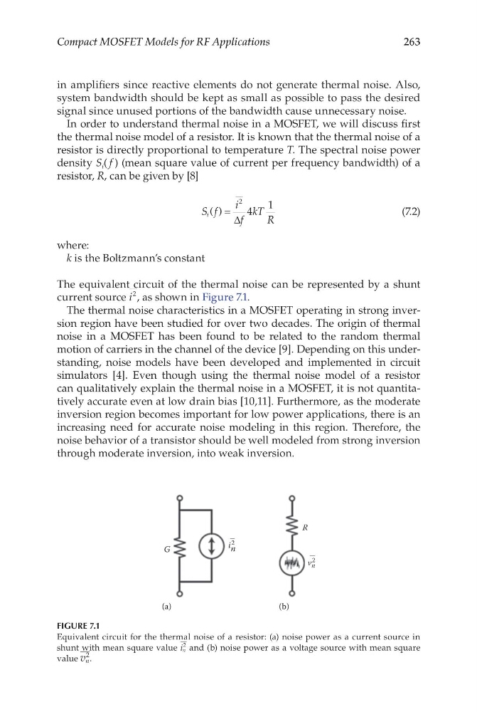
The equivalent circuit of the thermal noise can be represented by a shunt
current source i
2 , as shown in Figure 7.1.
The thermal noise characteristics in a MOSFET operating in strong inversion region have been studied for over two decades. The origin of thermal
noise in a MOSFET has been found to be related to the random thermal
motion of carriers in the channel of the device [9]. Depending on this understanding, noise models have been developed and implemented in circuit
simulators [4]. Even though using the thermal noise model of a resistor
can qualitatively explain the thermal noise in a MOSFET, it is not quantitatively accurate even at low drain bias [10,11]. Furthermore, as the moderate
inversion region becomes important for low power applications, there is an
increasing need for accurate noise modeling in this region. Therefore, the
noise behavior of a transistor should be well modeled from strong inversion
through moderate inversion, into weak inversion.
G
(a)
(b)
R
i n
2
—
v n
2
—
FIGURE 7.1
Equivalent circuit for the thermal noise of a resistor: (a) noise power as a current source in
shunt with mean square value i n
2 and (b) noise power as a voltage source with mean square
value v n
2 .
Compact MOSFET Models for RF Applications
in amplifiers since reactive elements do not generate thermal noise. Also,
system bandwidth should be kept as small as possible to pass the desired
signal since unused portions of the bandwidth cause unnecessary noise.
In order to understand thermal noise in a MOSFET, we will discuss first
the thermal noise model of a resistor. It is known that the thermal noise of a
resistor is directly proportional to temperature T. The spectral noise power
density S i ( f ) (mean square value of current per frequency bandwidth) of a
resistor, R, can be given by [8]
S f
i
f
kT R
i ( ) =
2
4
1
∆
(7.2)
where:
k is the Boltzmann’s constant
The equivalent circuit of the thermal noise can be represented by a shunt
current source i
2 , as shown in Figure 7.1.
The thermal noise characteristics in a MOSFET operating in strong inversion region have been studied for over two decades. The origin of thermal
noise in a MOSFET has been found to be related to the random thermal
motion of carriers in the channel of the device [9]. Depending on this understanding, noise models have been developed and implemented in circuit
simulators [4]. Even though using the thermal noise model of a resistor
can qualitatively explain the thermal noise in a MOSFET, it is not quantitatively accurate even at low drain bias [10,11]. Furthermore, as the moderate
inversion region becomes important for low power applications, there is an
increasing need for accurate noise modeling in this region. Therefore, the
noise behavior of a transistor should be well modeled from strong inversion
through moderate inversion, into weak inversion.
G
(a)
(b)
R
i n
2
—
v n
2
—
FIGURE 7.1
Equivalent circuit for the thermal noise of a resistor: (a) noise power as a current source in
shunt with mean square value i n
2 and (b) noise power as a voltage source with mean square
value v n
2 .