

241
MOSFET Capacitance Models
charge expressions for short channel devices. In general, the expressions for
Q i and Q b required for deriving the charge expressions (Equations 6.6 and
6.7) can be used from any DC current model for a MOSFET. However, in the
following section, the widely used regional DC current model in circuit CAD
tools is used to derive the expressions for charge-based capacitance model.
6.3.1 Long Channel Charge Model
In this section, the terminal charges are derived using the regional DC current model discussed in Section 4.4.4. Thus, similar to drain current model,
the charge-based model also consists of different expressions for terminal
charges for different regions of device operations.
6.3.1.1 Strong Inversion
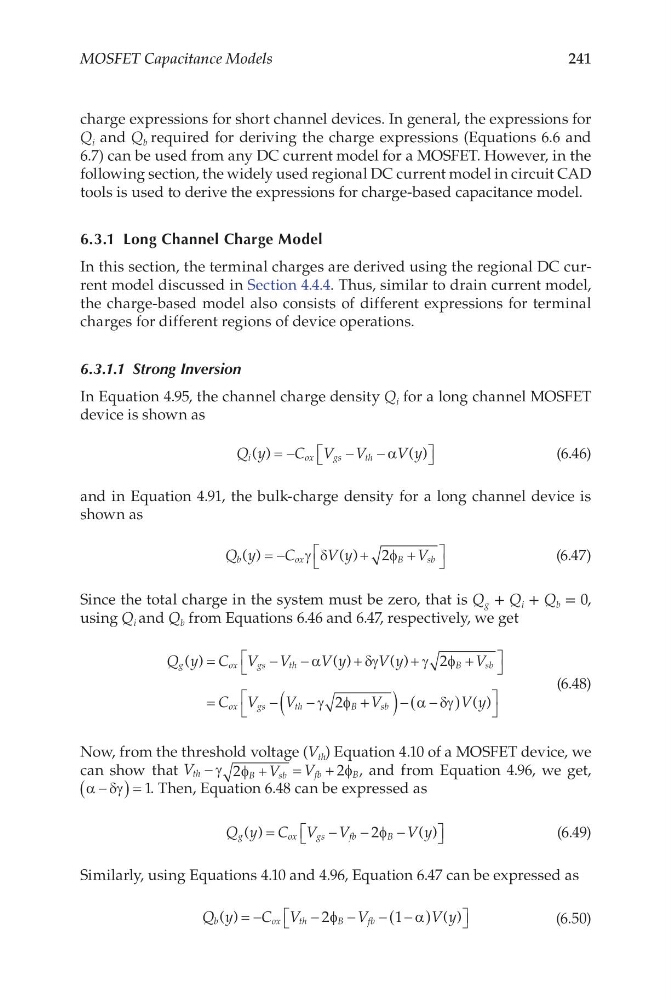
In Equation 4.95, the channel charge density Q i for a long channel MOSFET
device is shown as
Q y
C V V
V y
i
o x
g s
t h
( )
( )
= −
−
−
α
(6.46)
and in Equation 4.91, the bulk-charge density for a long channel device is
shown as
Q y
C
V y
V
b
o x
B
sb
( )
( )
= −
+
+
γ δ
φ
2
(6.47)
Since the total charge in the system must be zero, that is Q g + Q i + Q b = 0,
using Q i and Q b from Equations 6.46 and 6.47, respectively, we get
Q y C V V
V y
V y
V
C V
V
g
o x
g s
t h
Bsb
ox
gs
th
B
( )
( )
( )
=
−
−
+
+
+
=
−
−
α
δγ
γ φ
γ φ
2
2 + +
(
) − −
(
)
V
Vy
sb
α δγ ( )
(6.48)
Now, from the threshold voltage (V th ) Equation 4.10 of a MOSFET device, we
can show that V
V
V
th
B
s b
fb
B
−
+
=
+
γ φ
φ
2
2 , and from Equation 4.96, we get,
α δγ
−
(
)= 1. Then, Equation 6.48 can be expressed as
Q y C V V
Vy
g
o x
g s
f b
B
( )
( )
=
−
−
−
2φ
(6.49)
Similarly, using Equations 4.10 and 4.96, Equation 6.47 can be expressed as
Q y
C V
V
Vy
b
o x
t h
B
fb
( )
( )
= −
−
−
− −
(
)
2
1
φ
α
(6.50)
MOSFET Capacitance Models
charge expressions for short channel devices. In general, the expressions for
Q i and Q b required for deriving the charge expressions (Equations 6.6 and
6.7) can be used from any DC current model for a MOSFET. However, in the
following section, the widely used regional DC current model in circuit CAD
tools is used to derive the expressions for charge-based capacitance model.
6.3.1 Long Channel Charge Model
In this section, the terminal charges are derived using the regional DC current model discussed in Section 4.4.4. Thus, similar to drain current model,
the charge-based model also consists of different expressions for terminal
charges for different regions of device operations.
6.3.1.1 Strong Inversion
In Equation 4.95, the channel charge density Q i for a long channel MOSFET
device is shown as
Q y
C V V
V y
i
o x
g s
t h
( )
( )
= −
−
−
α
(6.46)
and in Equation 4.91, the bulk-charge density for a long channel device is
shown as
Q y
C
V y
V
b
o x
B
sb
( )
( )
= −
+
+
γ δ
φ
2
(6.47)
Since the total charge in the system must be zero, that is Q g + Q i + Q b = 0,
using Q i and Q b from Equations 6.46 and 6.47, respectively, we get
Q y C V V
V y
V y
V
C V
V
g
o x
g s
t h
Bsb
ox
gs
th
B
( )
( )
( )
=
−
−
+
+
+
=
−
−
α
δγ
γ φ
γ φ
2
2 + +
(
) − −
(
)
V
Vy
sb
α δγ ( )
(6.48)
Now, from the threshold voltage (V th ) Equation 4.10 of a MOSFET device, we
can show that V
V
V
th
B
s b
fb
B
−
+
=
+
γ φ
φ
2
2 , and from Equation 4.96, we get,
α δγ
−
(
)= 1. Then, Equation 6.48 can be expressed as
Q y C V V
Vy
g
o x
g s
f b
B
( )
( )
=
−
−
−
2φ
(6.49)
Similarly, using Equations 4.10 and 4.96, Equation 6.47 can be expressed as
Q y
C V
V
Vy
b
o x
t h
B
fb
( )
( )
= −
−
−
− −
(
)
2
1
φ
α
(6.50)