

238
Compact Models for Integrated Circuit Design
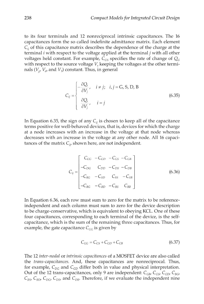
to its four terminals and 12 nonreciprocal intrinsic capacitances. The 16
capacitances form the so called indefinite admittance matrix. Each element
C ij of this capacitance matrix describes the dependence of the charge at the
terminal i with respect to the voltage applied at the terminal j with all other
voltages held constant. For example, C GS specifies the rate of change of Q G
with respect to the source voltage V s keeping the voltages at the other terminals (V g , V d , and V b ) constant. Thus, in general
C
Q
V
i j i j
Q
V
i j
ij
i
j
i
j
=
−
∂
∂
≠
=
∂
∂
=
,
; ,
,
G, S, D, B
(6.35)
In Equation 6.35, the sign of any C ij is chosen to keep all of the capacitance
terms positive for well-behaved devices, that is, devices for which the charge
at a node increases with an increase in the voltage at that node whereas
decreases with an increase in the voltage at any other node. All 16 capacitances of the matrix C ij , shown here, are not independent.
C
C
C
C
C
C
C
C
C
C
ij
GG
GD
GS
GB
DG
DD
DS
DB
=
−
−
−
−
−
−
− S SG
SD
SS
SB
BG
BD
BS
BB
C
C
C
C
C
C
C
−
−
−
−
−
(6.36)
In Equation 6.36, each row must sum to zero for the matrix to be referenceindependent and each column must sum to zero for the device description
to be charge-conservative, which is equivalent to obeying KCL. One of these
four capacitances, corresponding to each terminal of the device, is the selfcapacitance, which is the sum of the remaining three capacitances. Thus, for
example, the gate capacitance C GG is given by
C
C
C
C
GG
GS
GD
GB
=
+
+
(6.37)
The 12 inter-nodal or intrinsic capacitances of a MOSFET device are also called
the trans-capacitances. And, these capacitances are nonreciprocal. Thus,
for example, C DG and C GD differ both in value and physical interpretation.
Out of the 12 trans-capacitances, only 9 are independent: C GB , C GS , C GD , C BG ,
C BS , C BD , C DG , C DS , and C DB . Therefore, if we evaluate the independent nine
Compact Models for Integrated Circuit Design
to its four terminals and 12 nonreciprocal intrinsic capacitances. The 16
capacitances form the so called indefinite admittance matrix. Each element
C ij of this capacitance matrix describes the dependence of the charge at the
terminal i with respect to the voltage applied at the terminal j with all other
voltages held constant. For example, C GS specifies the rate of change of Q G
with respect to the source voltage V s keeping the voltages at the other terminals (V g , V d , and V b ) constant. Thus, in general
C
Q
V
i j i j
Q
V
i j
ij
i
j
i
j
=
−
∂
∂
≠
=
∂
∂
=
,
; ,
,
G, S, D, B
(6.35)
In Equation 6.35, the sign of any C ij is chosen to keep all of the capacitance
terms positive for well-behaved devices, that is, devices for which the charge
at a node increases with an increase in the voltage at that node whereas
decreases with an increase in the voltage at any other node. All 16 capacitances of the matrix C ij , shown here, are not independent.
C
C
C
C
C
C
C
C
C
C
ij
GG
GD
GS
GB
DG
DD
DS
DB
=
−
−
−
−
−
−
− S SG
SD
SS
SB
BG
BD
BS
BB
C
C
C
C
C
C
C
−
−
−
−
−
(6.36)
In Equation 6.36, each row must sum to zero for the matrix to be referenceindependent and each column must sum to zero for the device description
to be charge-conservative, which is equivalent to obeying KCL. One of these
four capacitances, corresponding to each terminal of the device, is the selfcapacitance, which is the sum of the remaining three capacitances. Thus, for
example, the gate capacitance C GG is given by
C
C
C
C
GG
GS
GD
GB
=
+
+
(6.37)
The 12 inter-nodal or intrinsic capacitances of a MOSFET device are also called
the trans-capacitances. And, these capacitances are nonreciprocal. Thus,
for example, C DG and C GD differ both in value and physical interpretation.
Out of the 12 trans-capacitances, only 9 are independent: C GB , C GS , C GD , C BG ,
C BS , C BD , C DG , C DS , and C DB . Therefore, if we evaluate the independent nine