

237
MOSFET Capacitance Models
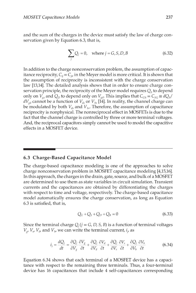
and the sum of the charges in the device must satisfy the law of charge conservation given by Equation 6.3, that is,
Q
j G S D B
j
j
∑ =
=
0,
, , ,
where
(6.32)
In addition to the charge nonconservation problem, the assumption of capacitance reciprocity, C ij = C ji , in the Meyer model is more critical. It is shown that
the assumption of reciprocity is inconsistent with the charge conservation
law [13,14]. The detailed analysis shows that in order to ensure charge conservation principle, the reciprocity of the Meyer model requires Q S to depend
only on V gs and Q D to depend only on V gd . This implies that C GS = C SG ≡ dQ S /
dV gd cannot be a function of V ds or V bs [14]. In reality, the channel charge can
be modulated by both V ds and V bs . Therefore, the assumption of capacitance
reciprocity is nonphysical. The nonreciprocal effect in MOSFETs is due to the
fact that the channel charge is controlled by three or more terminal voltages.
And, the reciprocal capacitors simply cannot be used to model the capacitive
effects in a MOSFET device.
6.3 Charge-Based Capacitance Model
The charge-based capacitance modeling is one of the approaches to solve
charge nonconservation problem in MOSFET capacitance modeling [4,15,16].
In this approach, the charges in the drain, gate, source, and bulk of a MOSFET
are determined to use them as state variables in circuit simulation. Transient
currents and the capacitances are obtained by differentiating the charges
with respect to time and voltage, respectively. The charge-based capacitance
model automatically ensures the charge conservation, as long as Equation
6.3 is satisfied, that is,
Q Q Q Q
G
S
D
B
+ +
+
=0
(6.33)
Since the terminal charge Q j (j = G, D, S, B) is a function of terminal voltages
V g , V s , V d , and V b , we can write the terminal current, i j , as
i
dQ
dt
Q
V
V
t
Q
V
V
t
Q
V
V
t
Q
V
V
t
j
j
j
g
g
j
d
d
j
s
s
j
b
b
=
=
∂
∂
∂
∂
+
∂
∂
∂
∂
+
∂
∂
∂
∂
+
∂
∂
∂
∂
(6.34)
Equation 6.34 shows that each terminal of a MOSFET device has a capacitance with respect to the remaining three terminals. Thus, a four-terminal
device has 16 capacitances that include 4 self-capacitances corresponding
MOSFET Capacitance Models
and the sum of the charges in the device must satisfy the law of charge conservation given by Equation 6.3, that is,
Q
j G S D B
j
j
∑ =
=
0,
, , ,
where
(6.32)
In addition to the charge nonconservation problem, the assumption of capacitance reciprocity, C ij = C ji , in the Meyer model is more critical. It is shown that
the assumption of reciprocity is inconsistent with the charge conservation
law [13,14]. The detailed analysis shows that in order to ensure charge conservation principle, the reciprocity of the Meyer model requires Q S to depend
only on V gs and Q D to depend only on V gd . This implies that C GS = C SG ≡ dQ S /
dV gd cannot be a function of V ds or V bs [14]. In reality, the channel charge can
be modulated by both V ds and V bs . Therefore, the assumption of capacitance
reciprocity is nonphysical. The nonreciprocal effect in MOSFETs is due to the
fact that the channel charge is controlled by three or more terminal voltages.
And, the reciprocal capacitors simply cannot be used to model the capacitive
effects in a MOSFET device.
6.3 Charge-Based Capacitance Model
The charge-based capacitance modeling is one of the approaches to solve
charge nonconservation problem in MOSFET capacitance modeling [4,15,16].
In this approach, the charges in the drain, gate, source, and bulk of a MOSFET
are determined to use them as state variables in circuit simulation. Transient
currents and the capacitances are obtained by differentiating the charges
with respect to time and voltage, respectively. The charge-based capacitance
model automatically ensures the charge conservation, as long as Equation
6.3 is satisfied, that is,
Q Q Q Q
G
S
D
B
+ +
+
=0
(6.33)
Since the terminal charge Q j (j = G, D, S, B) is a function of terminal voltages
V g , V s , V d , and V b , we can write the terminal current, i j , as
i
dQ
dt
Q
V
V
t
Q
V
V
t
Q
V
V
t
Q
V
V
t
j
j
j
g
g
j
d
d
j
s
s
j
b
b
=
=
∂
∂
∂
∂
+
∂
∂
∂
∂
+
∂
∂
∂
∂
+
∂
∂
∂
∂
(6.34)
Equation 6.34 shows that each terminal of a MOSFET device has a capacitance with respect to the remaining three terminals. Thus, a four-terminal
device has 16 capacitances that include 4 self-capacitances corresponding