

231
MOSFET Capacitance Models
where:
Q B = WLQ b
Equation 6.11 is the generalized expression for Q G in a MOSFET device.
In order to calculate Q G from Equation 6.11, any expression for Q i used to calculate I ds can be used. However, in deriving the Meyer intrinsic capacitance
model, long channel expressions for Q i and Q b from Chapter 4 are used
to derive Q G and the capacitances in the different mode of operations of
MOSFET devices as described next.
6.2.2.1 Strong Inversion
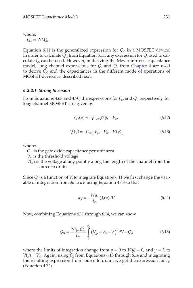
From Equations 4.68 and 4.70, the expressions for Q b and Q i , respectively, for
long channel MOSFETs are given by
Q y
C
V
b
o x
B
sb
( ) = −
+
γ
φ
2
(6.12)
Q y
C V V V y
i
o x
g s
t h
( )
( )
= −
−
−
(6.13)
where:
C ox is the gate oxide capacitance per unit area
V th is the threshold voltage
V(y) is the voltage at any point y along the length of the channel from the
source to drain
Since Q i is a function of V, to integrate Equation 6.11 we first change the variable of integration from dy to dV using Equation 4.63 so that
dy
W
I
Q y dV
s
ds
i
= −
µ
( )
(6.14)
Now, combining Equations 6.11 through 6.14, we can show
Q
W C
I
V V V dV Q
G
s ox
ds
gs
th
V
B
ds
=
−
−
(
) −
∫
2
2
2
0
µ
(6.15)
where the limits of integration change from y = 0 to V(y) = 0, and y = L to
V(y) = V ds . Again, using Q i from Equations 6.13 through 6.14 and integrating
the resulting expression from source to drain, we get the expression for I ds
(Equation 4.72)
MOSFET Capacitance Models
where:
Q B = WLQ b
Equation 6.11 is the generalized expression for Q G in a MOSFET device.
In order to calculate Q G from Equation 6.11, any expression for Q i used to calculate I ds can be used. However, in deriving the Meyer intrinsic capacitance
model, long channel expressions for Q i and Q b from Chapter 4 are used
to derive Q G and the capacitances in the different mode of operations of
MOSFET devices as described next.
6.2.2.1 Strong Inversion
From Equations 4.68 and 4.70, the expressions for Q b and Q i , respectively, for
long channel MOSFETs are given by
Q y
C
V
b
o x
B
sb
( ) = −
+
γ
φ
2
(6.12)
Q y
C V V V y
i
o x
g s
t h
( )
( )
= −
−
−
(6.13)
where:
C ox is the gate oxide capacitance per unit area
V th is the threshold voltage
V(y) is the voltage at any point y along the length of the channel from the
source to drain
Since Q i is a function of V, to integrate Equation 6.11 we first change the variable of integration from dy to dV using Equation 4.63 so that
dy
W
I
Q y dV
s
ds
i
= −
µ
( )
(6.14)
Now, combining Equations 6.11 through 6.14, we can show
Q
W C
I
V V V dV Q
G
s ox
ds
gs
th
V
B
ds
=
−
−
(
) −
∫
2
2
2
0
µ
(6.15)
where the limits of integration change from y = 0 to V(y) = 0, and y = L to
V(y) = V ds . Again, using Q i from Equations 6.13 through 6.14 and integrating
the resulting expression from source to drain, we get the expression for I ds
(Equation 4.72)