

232
Compact Models for Integrated Circuit Design
I
C
W
L
V V
V V
V
V
ds
s ox
g s
t h
ds
ds
gs
th
=
−
−
>
µ
2
;
(6.16)
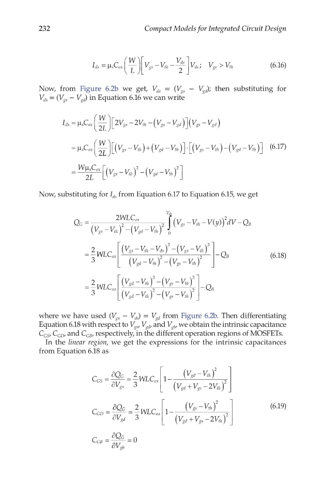
Now, from Figure 6.2b we get, V ds = (V gs − V gd ); then substituting for
V ds = (V gs − V gd ) in Equation 6.16 we can write
I
C
W
L
V
V
V V
V V
C
W
ds
s ox
g s
t h
g s
g d
g s
g d
s ox
=
−
−
−
(
)
−
(
)
=
µ
µ
2
2
2
2L L
V V
V V
V V
V V
W
gs
th
gd
th
gs
th
gd
th
−
(
) + −
(
)
⋅
−
(
) − −
(
)
=
µ s s ox
gs
th
gd
th
C
L
V V
V V
2
2
2
−
(
) − −
(
)
(6.17)
Now, substituting for I ds from Equation 6.17 to Equation 6.15, we get
Q
WLC
V V
V V
V V V y dV Q
G
ox
gs
th
gd
th
gs
th
V
B
ds
=
−
(
) − −
(
)
−
−
(
) −
=
∫
2
2
3
2
2
2
0
( )
W WLC
V V V
V V
V V
V V
ox
gs
th
ds
gs
th
gd
th
gs
th
−
−
(
) − −
(
)
−
(
) − −
(
)
3
3
2
2
−
=
−
(
) − −
(
)
−
(
) − −
(
)
Q
WLC
V V
V V
V V
V V
B
ox
gd
th
gs
th
gd
th
gs
th
2
3
3
3
2
2
− Q B
(6.18)
where we have used (V gs − V ds ) = V gd from Figure 6.2b. Then differentiating
Equation 6.18 with respect to V gs , V gd , and V gb , we obtain the intrinsic capacitance
C GS , C GD , and C GB , respectively, in the different operation regions of MOSFETs.
In the linear region, we get the expressions for the intrinsic capacitances
from Equation 6.18 as
C
Q
V
WLC
V V
V
V
V
C
GS
G
gs
ox
gd
th
gd
gs
th
GD
=
∂
∂
=
−
−
(
)
+
−
(
)
=
2
3
1
2
2
2
∂ ∂
∂
=
−
−
(
)
+
−
(
)
=
∂
Q
V
WLC
V V
V
V
V
C
Q
G
gd
ox
gs
th
gd
gs
th
GB
G
2
3
1
2
2
2
∂ ∂
=
V gb
0
(6.19)
Compact Models for Integrated Circuit Design
I
C
W
L
V V
V V
V
V
ds
s ox
g s
t h
ds
ds
gs
th
=
−
−
>
µ
2
;
(6.16)
Now, from Figure 6.2b we get, V ds = (V gs − V gd ); then substituting for
V ds = (V gs − V gd ) in Equation 6.16 we can write
I
C
W
L
V
V
V V
V V
C
W
ds
s ox
g s
t h
g s
g d
g s
g d
s ox
=
−
−
−
(
)
−
(
)
=
µ
µ
2
2
2
2L L
V V
V V
V V
V V
W
gs
th
gd
th
gs
th
gd
th
−
(
) + −
(
)
⋅
−
(
) − −
(
)
=
µ s s ox
gs
th
gd
th
C
L
V V
V V
2
2
2
−
(
) − −
(
)
(6.17)
Now, substituting for I ds from Equation 6.17 to Equation 6.15, we get
Q
WLC
V V
V V
V V V y dV Q
G
ox
gs
th
gd
th
gs
th
V
B
ds
=
−
(
) − −
(
)
−
−
(
) −
=
∫
2
2
3
2
2
2
0
( )
W WLC
V V V
V V
V V
V V
ox
gs
th
ds
gs
th
gd
th
gs
th
−
−
(
) − −
(
)
−
(
) − −
(
)
3
3
2
2
−
=
−
(
) − −
(
)
−
(
) − −
(
)
Q
WLC
V V
V V
V V
V V
B
ox
gd
th
gs
th
gd
th
gs
th
2
3
3
3
2
2
− Q B
(6.18)
where we have used (V gs − V ds ) = V gd from Figure 6.2b. Then differentiating
Equation 6.18 with respect to V gs , V gd , and V gb , we obtain the intrinsic capacitance
C GS , C GD , and C GB , respectively, in the different operation regions of MOSFETs.
In the linear region, we get the expressions for the intrinsic capacitances
from Equation 6.18 as
C
Q
V
WLC
V V
V
V
V
C
GS
G
gs
ox
gd
th
gd
gs
th
GD
=
∂
∂
=
−
−
(
)
+
−
(
)
=
2
3
1
2
2
2
∂ ∂
∂
=
−
−
(
)
+
−
(
)
=
∂
Q
V
WLC
V V
V
V
V
C
Q
G
gd
ox
gs
th
gd
gs
th
GB
G
2
3
1
2
2
2
∂ ∂
=
V gb
0
(6.19)