

194
Compact Models for Integrated Circuit Design
the depletion region of a MOSFET device and μ eff becomes strong function
of channel doping concentration as observed experimentally. As the effective electric field increases, the phonon scattering due to lattice vibration
becomes important. Thus, phonon scattering is weakly dependent on vertical electric fields and has the strongest temperature dependence on μ eff as
shown in Figure 5.9b.
The previous physical analysis describes the behavior of μ eff versus E eff .
However, we need to develop an effective mobility model that can be
used in drain current calculation to account for the vertical field effects
on device performance. In order to develop μ eff model for circuit CAD, we
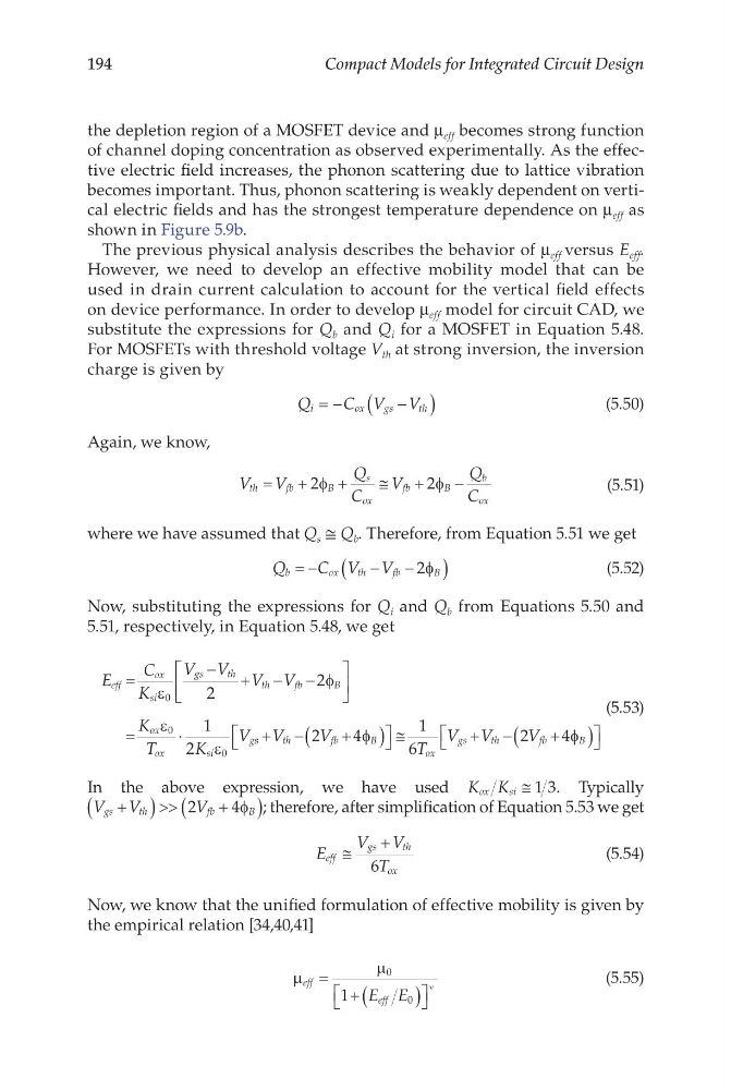
substitute the expressions for Q b and Q i for a MOSFET in Equation 5.48.
For MOSFETs with threshold voltage V th at strong inversion, the inversion
charge is given by
Q
C V V
i
o x
g s
t h
= −
−
(
)
(5.50)
Again, we know,
V V
Q
C
V
Q
C
th
fb
B
s
ox
fb
B
b
ox
=
+
+
+
−
2
2
φ
φ
≅
(5.51)
where we have assumed that Q s ≅ Q b . Therefore, from Equation 5.51 we get
Q
C V V
b
o x
t h
f b
B
= −
−
−
(
)
2φ
(5.52)
Now, substituting the expressions for Q i and Q b from Equations 5.50 and
5.51, respectively, in Equation 5.48, we get
E
C
K
V V V V
K
T
K
V
eff
ox
si
gs
th
th
fb
B
ox
ox
si
g
=
− + − −
=
⋅
ε
φ
ε
ε
0
0
0
2
2
1
2
s s
t h
f b
B
ox
gs
th
fb
B
V
V
T
V V
V
+ −
+
(
)
≅
+ −
+
(
)
2
4
1
6
2
4
φ
φ
(5.53)
In the above expression, we have used K K
ox
si ≅ 1 3. Typically
V V
V
gs
th
fb
B
+
(
) >>
+
(
)
2
4φ ; therefore, after simplification of Equation 5.53 we get
E
V V
T
eff
gs
th
ox
≅
+
6
(5.54)
Now, we know that the unified formulation of effective mobility is given by
the empirical relation [34,40,41]
µ
µ
eff
eff
E E
=
+ (
)
ν
0
0
1
(5.55)
Compact Models for Integrated Circuit Design
the depletion region of a MOSFET device and μ eff becomes strong function
of channel doping concentration as observed experimentally. As the effective electric field increases, the phonon scattering due to lattice vibration
becomes important. Thus, phonon scattering is weakly dependent on vertical electric fields and has the strongest temperature dependence on μ eff as
shown in Figure 5.9b.
The previous physical analysis describes the behavior of μ eff versus E eff .
However, we need to develop an effective mobility model that can be
used in drain current calculation to account for the vertical field effects
on device performance. In order to develop μ eff model for circuit CAD, we
substitute the expressions for Q b and Q i for a MOSFET in Equation 5.48.
For MOSFETs with threshold voltage V th at strong inversion, the inversion
charge is given by
Q
C V V
i
o x
g s
t h
= −
−
(
)
(5.50)
Again, we know,
V V
Q
C
V
Q
C
th
fb
B
s
ox
fb
B
b
ox
=
+
+
+
−
2
2
φ
φ
≅
(5.51)
where we have assumed that Q s ≅ Q b . Therefore, from Equation 5.51 we get
Q
C V V
b
o x
t h
f b
B
= −
−
−
(
)
2φ
(5.52)
Now, substituting the expressions for Q i and Q b from Equations 5.50 and
5.51, respectively, in Equation 5.48, we get
E
C
K
V V V V
K
T
K
V
eff
ox
si
gs
th
th
fb
B
ox
ox
si
g
=
− + − −
=
⋅
ε
φ
ε
ε
0
0
0
2
2
1
2
s s
t h
f b
B
ox
gs
th
fb
B
V
V
T
V V
V
+ −
+
(
)
≅
+ −
+
(
)
2
4
1
6
2
4
φ
φ
(5.53)
In the above expression, we have used K K
ox
si ≅ 1 3. Typically
V V
V
gs
th
fb
B
+
(
) >>
+
(
)
2
4φ ; therefore, after simplification of Equation 5.53 we get
E
V V
T
eff
gs
th
ox
≅
+
6
(5.54)
Now, we know that the unified formulation of effective mobility is given by
the empirical relation [34,40,41]
µ
µ
eff
eff
E E
=
+ (
)
ν
0
0
1
(5.55)