

195
Compact Models for Small Geometry MOSFETs
where:
μ 0 is concentration-dependent surface mobility
E 0 is the critical electric field
ν is a constant
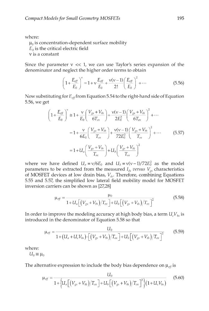
Since the parameter ν << 1, we can use Taylor’s series expansion of the
denominator and neglect the higher order terms to obtain
1
1
1
2
0
0
0
2
+
= +ν
+
ν ν −
+
ν
E
E
E
E
E
E
eff
e ff
eff
(
)
!
(5.56)
Now substituting for E eff from Equation 5.54 to the right-hand side of Equation
5.56, we get
1
1
6
1
2
6
0
0
0
2
+
≅ +
ν
+
+
ν ν −
+
ν
E
E
E
V V
T
E
V V
T
eff
gs
th
ox
gs
th
(
)
o ox
gs
th
ox
gs
th
ox
E
V V
T
E
V V
T
+
= +
ν
+
+
ν ν −
+
2
0
0
2
1 6
1
72
(
)
+
= +
+
+
+
2
2
1
U
V V
T
U
V V
T
a
gs
th
ox
b
gs
th
ox
(5.57)
where we have defined U
E
a ≡ ν/6 0 and U
E
b ≡ ν ν −
(
) /
1 2 0
2
7
as the model
parameters to be extracted from the measured I ds versus V gs characteristics
of MOSFET devices at low drain bias, V ds . Therefore, combining Equations
5.55 and 5.57, the simplified low lateral field mobility model for MOSFET
inversion carriers can be shown as [27,28]
µ
µ
eff
a
g s
t h
o x
b
gs
th
ox
U V V T
U V V T
=
+
+
(
)
+
+
(
)
0
2
1
(5.58)
In order to improve the modeling accuracy at high body bias, a term U c V bs is
introduced in the denominator of Equation 5.58 so that
µ eff
a
c bs
gs
th
ox
b
g s
t h
o x
U
U U V
V V T
U V V T
=
+
+
(
)⋅
+
(
)
+
+
(
)
0
2
1
(5.59)
where:
U 0 ≡ μ 0
The alternative expression to include the body bias dependence on μ eff is
µ eff
a
g s
t h
o x
b
gs
th
ox
c bs
U
U V V T
U V V T
U V
=
+
+
(
)
+
+
(
)
{
} +
(
)
0
2
1
1
(5.60)
Compact Models for Small Geometry MOSFETs
where:
μ 0 is concentration-dependent surface mobility
E 0 is the critical electric field
ν is a constant
Since the parameter ν << 1, we can use Taylor’s series expansion of the
denominator and neglect the higher order terms to obtain
1
1
1
2
0
0
0
2
+
= +ν
+
ν ν −
+
ν
E
E
E
E
E
E
eff
e ff
eff
(
)
!
(5.56)
Now substituting for E eff from Equation 5.54 to the right-hand side of Equation
5.56, we get
1
1
6
1
2
6
0
0
0
2
+
≅ +
ν
+
+
ν ν −
+
ν
E
E
E
V V
T
E
V V
T
eff
gs
th
ox
gs
th
(
)
o ox
gs
th
ox
gs
th
ox
E
V V
T
E
V V
T
+
= +
ν
+
+
ν ν −
+
2
0
0
2
1 6
1
72
(
)
+
= +
+
+
+
2
2
1
U
V V
T
U
V V
T
a
gs
th
ox
b
gs
th
ox
(5.57)
where we have defined U
E
a ≡ ν/6 0 and U
E
b ≡ ν ν −
(
) /
1 2 0
2
7
as the model
parameters to be extracted from the measured I ds versus V gs characteristics
of MOSFET devices at low drain bias, V ds . Therefore, combining Equations
5.55 and 5.57, the simplified low lateral field mobility model for MOSFET
inversion carriers can be shown as [27,28]
µ
µ
eff
a
g s
t h
o x
b
gs
th
ox
U V V T
U V V T
=
+
+
(
)
+
+
(
)
0
2
1
(5.58)
In order to improve the modeling accuracy at high body bias, a term U c V bs is
introduced in the denominator of Equation 5.58 so that
µ eff
a
c bs
gs
th
ox
b
g s
t h
o x
U
U U V
V V T
U V V T
=
+
+
(
)⋅
+
(
)
+
+
(
)
0
2
1
(5.59)
where:
U 0 ≡ μ 0
The alternative expression to include the body bias dependence on μ eff is
µ eff
a
g s
t h
o x
b
gs
th
ox
c bs
U
U V V T
U V V T
U V
=
+
+
(
)
+
+
(
)
{
} +
(
)
0
2
1
1
(5.60)