

193
Compact Models for Small Geometry MOSFETs
10
4
2
(a)
400
500
600
700
U n i v e r s a l b e h a v i o r
μ
eff (cm 2
/V-sec)
800
900
1.22 × 10 15
1.3 × 10
16
1.4 × 10
17
N A = 3 × 10 14 cm
−3
(100)
Q f = 1.0 × 10 11 cm
−2
4
E eff (V/cm)
6 8
2
4
10
5
Total mobility
(b)
P h o n o n sc a tt e ri n g
S u r f a c e
r o u g h n e s s
s c a t t e r i n g
C o u l o m
b
s c a t t e r i n g
High
temperatures
Effective normal electric field
Low
temperature
Mobility
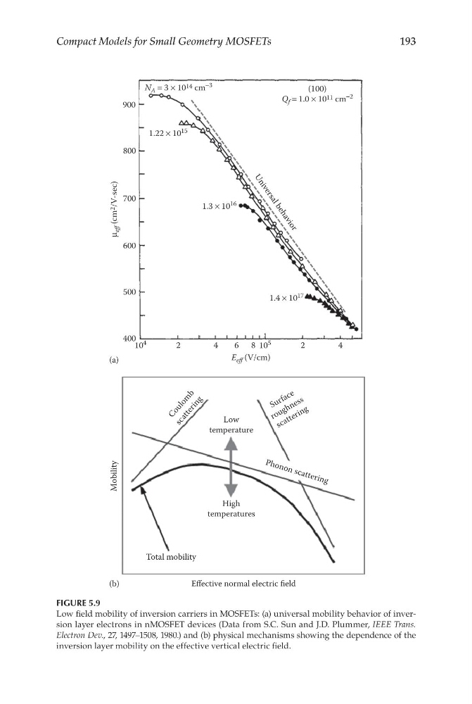
FIGURE 5.9
Low field mobility of inversion carriers in MOSFETs: (a) universal mobility behavior of inversion layer electrons in nMOSFET devices (Data from S.C. Sun and J.D. Plummer, IEEE Trans.
Electron Dev., 27, 1497–1508, 1980.) and (b) physical mechanisms showing the dependence of the
inversion layer mobility on the effective vertical electric field.
Compact Models for Small Geometry MOSFETs
10
4
2
(a)
400
500
600
700
U n i v e r s a l b e h a v i o r
μ
eff (cm 2
/V-sec)
800
900
1.22 × 10 15
1.3 × 10
16
1.4 × 10
17
N A = 3 × 10 14 cm
−3
(100)
Q f = 1.0 × 10 11 cm
−2
4
E eff (V/cm)
6 8
2
4
10
5
Total mobility
(b)
P h o n o n sc a tt e ri n g
S u r f a c e
r o u g h n e s s
s c a t t e r i n g
C o u l o m
b
s c a t t e r i n g
High
temperatures
Effective normal electric field
Low
temperature
Mobility
FIGURE 5.9
Low field mobility of inversion carriers in MOSFETs: (a) universal mobility behavior of inversion layer electrons in nMOSFET devices (Data from S.C. Sun and J.D. Plummer, IEEE Trans.
Electron Dev., 27, 1497–1508, 1980.) and (b) physical mechanisms showing the dependence of the
inversion layer mobility on the effective vertical electric field.