

168
Compact Models for Integrated Circuit Design
Subthreshold slope: An important characteristic of the subthreshold region is
the gate voltage swing required to reduce the current from its ON value to an
acceptable OFF value. This gate voltage is also called the subthreshold slope S
or SS or S-factor. It is the inverse of the slope of I ds − V gs characteristics and is
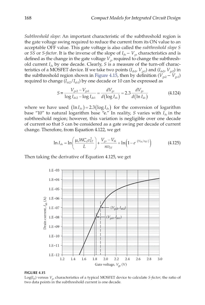
defined as the change in the gate voltage V gs required to change the subthreshold current I ds by one decade. Clearly, S is a measure of the turn-off characteristics of a MOSFET device. If we take two points (I ds1 , V gs1 ) and (I ds2 , V gs2 ) in
the subthreshold region shown in Figure 4.15, then by definition (V gs2 − V gs1 )
required to change (I ds2 /I ds1 ) by one decade or 10 can be expressed as
S
V
V
I
I
dV
d
I
dV
d
I
gs
gs
ds
ds
gs
ds
gs
ds
≡
−
−
=
(
)
=
(
)
2
1
2
1
2 3
log
log
log
.
ln
(4.124)
where we have used ln
. log
I
I
ds
ds
(
)= (
)
2 3
for the conversion of logarithm
base “10” to natural logarithm base “e.” In reality, S varies with I ds in the
subthreshold region; however, this variation is negligible over one decade
of current so that S can be considered as a gate swing per decade of current
change. Therefore, from Equation 4.122, we get
ln
ln
ln
I
WC v
L
V V
nv
e
ds
s
d kT
gs
th
kT
V v
ds kT
=
+
−
+
−
(
)
−(
)
µ
2
1
(4.125)
Then taking the derivative of Equation 4.125, we get
1.2
1.E−12
1.E−11
1.E−10
1.E−09
1.E−08
1.E−07
Drain current, I
ds (A)
1.E−06
1.E−05
1.E−04
1.E−03
1.4
1.6
1.8
2.0
Gate voltage, V gs (V)
2.2
(V gs1 , I ds1 )
(V gs2 , I ds2 )
2.4
2.6
2.8
3.0
FIGURE 4.15
Log(I ds ) versus V gs characteristics of a typical MOSFET device to calculate S-factor; the ratio of
two data points in the subthreshold current is one decade.
Compact Models for Integrated Circuit Design
Subthreshold slope: An important characteristic of the subthreshold region is
the gate voltage swing required to reduce the current from its ON value to an
acceptable OFF value. This gate voltage is also called the subthreshold slope S
or SS or S-factor. It is the inverse of the slope of I ds − V gs characteristics and is
defined as the change in the gate voltage V gs required to change the subthreshold current I ds by one decade. Clearly, S is a measure of the turn-off characteristics of a MOSFET device. If we take two points (I ds1 , V gs1 ) and (I ds2 , V gs2 ) in
the subthreshold region shown in Figure 4.15, then by definition (V gs2 − V gs1 )
required to change (I ds2 /I ds1 ) by one decade or 10 can be expressed as
S
V
V
I
I
dV
d
I
dV
d
I
gs
gs
ds
ds
gs
ds
gs
ds
≡
−
−
=
(
)
=
(
)
2
1
2
1
2 3
log
log
log
.
ln
(4.124)
where we have used ln
. log
I
I
ds
ds
(
)= (
)
2 3
for the conversion of logarithm
base “10” to natural logarithm base “e.” In reality, S varies with I ds in the
subthreshold region; however, this variation is negligible over one decade
of current so that S can be considered as a gate swing per decade of current
change. Therefore, from Equation 4.122, we get
ln
ln
ln
I
WC v
L
V V
nv
e
ds
s
d kT
gs
th
kT
V v
ds kT
=
+
−
+
−
(
)
−(
)
µ
2
1
(4.125)
Then taking the derivative of Equation 4.125, we get
1.2
1.E−12
1.E−11
1.E−10
1.E−09
1.E−08
1.E−07
Drain current, I
ds (A)
1.E−06
1.E−05
1.E−04
1.E−03
1.4
1.6
1.8
2.0
Gate voltage, V gs (V)
2.2
(V gs1 , I ds1 )
(V gs2 , I ds2 )
2.4
2.6
2.8
3.0
FIGURE 4.15
Log(I ds ) versus V gs characteristics of a typical MOSFET device to calculate S-factor; the ratio of
two data points in the subthreshold current is one decade.