

146
Compact Models for Integrated Circuit Design
circuit CAD. Therefore, various simplifications of PaoSah model have been
used to develop computationally efficient compact models suitable for circuit
analysis [3–5,12–22]. PaoSah model is used to benchmark the accuracy of
other simplified models.
4.4.3 Charge-Sheet Model
In order to derive an accurate and simplified I ds model from the generalized
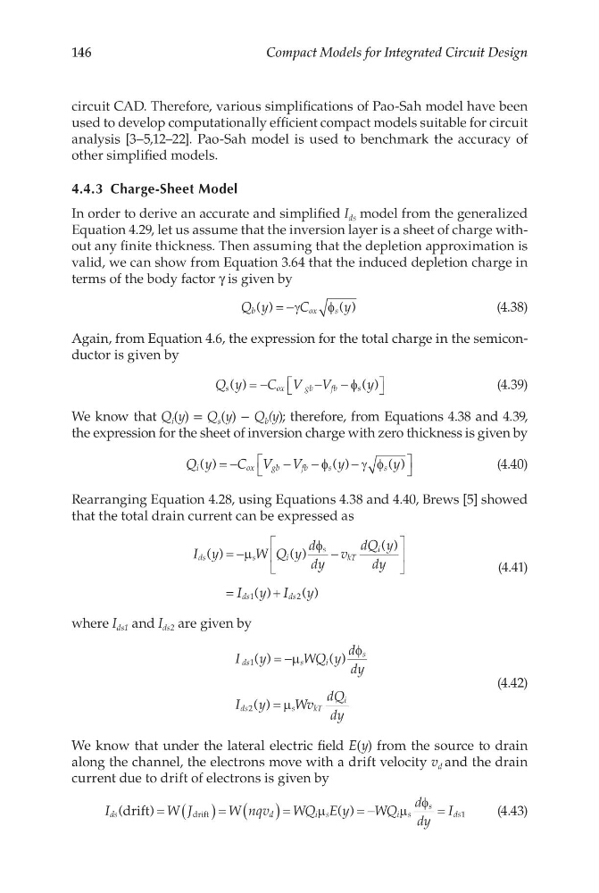
Equation 4.29, let us assume that the inversion layer is a sheet of charge without any finite thickness. Then assuming that the depletion approximation is
valid, we can show from Equation 3.64 that the induced depletion charge in
terms of the body factor γ is given by
Q y
C
y
b
o x
s
( )
( )
= −γ
φ
(4.38)
Again, from Equation 4.6, the expression for the total charge in the semiconductor is given by
Q y
C V V
y
s
o x
g b
f b
s
( )
( )
= −
− −
φ
(4.39)
We know that Q i (y) = Q s (y) − Q b (y); therefore, from Equations 4.38 and 4.39,
the expression for the sheet of inversion charge with zero thickness is given by
Q y
C V V
y
y
i
o x
g b
f b
s
s
( )
( )
( )
= −
−
−
−
φ
γ φ
(4.40)
Rearranging Equation 4.28, using Equations 4.38 and 4.40, Brews [5] showed
that the total drain current can be expressed as
I y
W Q y
d
dy
v
dQ y
dy
I y I y
ds
s
i
s
kT
i
ds
ds
( )
( )
( )
( )
( )
= −
−
=
+
µ
φ
1
2
(4.41)
where I ds1 and I ds2 are given by
I y
WQ y
d
dy
I y
Wv
dQ
dy
ds
s
i
s
ds
s
k T
i
1
2
( )
( )
( )
= −
=
µ
φ
µ
(4.42)
We know that under the lateral electric field E(y) from the source to drain
along the channel, the electrons move with a drift velocity v d and the drain
current due to drift of electrons is given by
I
W J
W nqv
WQ E y
WQ
d
dy
I
ds
d
i s
is
s
ds
(
)
( )
drift
drift
= ( )= ( )=
=−
=
µ
µ
φ
1
(4.43)
Compact Models for Integrated Circuit Design
circuit CAD. Therefore, various simplifications of PaoSah model have been
used to develop computationally efficient compact models suitable for circuit
analysis [3–5,12–22]. PaoSah model is used to benchmark the accuracy of
other simplified models.
4.4.3 Charge-Sheet Model
In order to derive an accurate and simplified I ds model from the generalized
Equation 4.29, let us assume that the inversion layer is a sheet of charge without any finite thickness. Then assuming that the depletion approximation is
valid, we can show from Equation 3.64 that the induced depletion charge in
terms of the body factor γ is given by
Q y
C
y
b
o x
s
( )
( )
= −γ
φ
(4.38)
Again, from Equation 4.6, the expression for the total charge in the semiconductor is given by
Q y
C V V
y
s
o x
g b
f b
s
( )
( )
= −
− −
φ
(4.39)
We know that Q i (y) = Q s (y) − Q b (y); therefore, from Equations 4.38 and 4.39,
the expression for the sheet of inversion charge with zero thickness is given by
Q y
C V V
y
y
i
o x
g b
f b
s
s
( )
( )
( )
= −
−
−
−
φ
γ φ
(4.40)
Rearranging Equation 4.28, using Equations 4.38 and 4.40, Brews [5] showed
that the total drain current can be expressed as
I y
W Q y
d
dy
v
dQ y
dy
I y I y
ds
s
i
s
kT
i
ds
ds
( )
( )
( )
( )
( )
= −
−
=
+
µ
φ
1
2
(4.41)
where I ds1 and I ds2 are given by
I y
WQ y
d
dy
I y
Wv
dQ
dy
ds
s
i
s
ds
s
k T
i
1
2
( )
( )
( )
= −
=
µ
φ
µ
(4.42)
We know that under the lateral electric field E(y) from the source to drain
along the channel, the electrons move with a drift velocity v d and the drain
current due to drift of electrons is given by
I
W J
W nqv
WQ E y
WQ
d
dy
I
ds
d
i s
is
s
ds
(
)
( )
drift
drift
= ( )= ( )=
=−
=
µ
µ
φ
1
(4.43)