

120
Compact Models for Integrated Circuit Design
This is a nonequilibrium condition under which the depletion width continues to widen beyond its maximum value, X dmax , in order to balance the
increased gate charge and C does not reach a minimum. This expansion of
the depletion region deep into the substrate is referred to as the deep depletion.
From Equation 3.98, the capacitance in the deep depletion mode is given by
C
K
X
C
C V V qK N
si
d
ox
ox
g
f b
s i
b
=
=
+
−
(
)
(
)
ε
ε
0
2
0
1 2
deep depletion
(3.104)
The capacitance in the deep depletion is obtained when the rate of DC voltage sweep is high, independent of the frequency of the AC signal voltage
(HF) and no inversion charge can form. The easiest way to obtain deep depletion
is to sweep the DC voltage by either applying a voltage step or using a fast voltage
ramp on the gate.
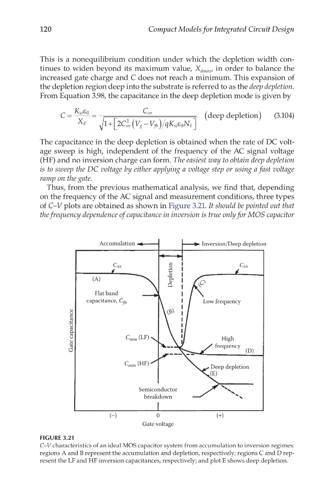
Thus, from the previous mathematical analysis, we find that, depending
on the frequency of the AC signal and measurement conditions, three types
of C–V plots are obtained as shown in Figure 3.21. It should be pointed out that
the frequency dependence of capacitance in inversion is true only for MOS capacitor
Accumulation
Gate capacitance
Cox
Cox
(A)
(E)
(D)
( C )
(B )
Flat band
capacitance, C fb
C min (LF)
C min (HF)
Semiconductor
breakdown
0
Gate voltage
Deep depletion
High
frequency
Low frequency
Depletion
(+)
(−)
Inversion/Deep depletion
FIGURE 3.21
C–V characteristics of an ideal MOS capacitor system from accumulation to inversion regimes:
regions A and B represent the accumulation and depletion, respectively; regions C and D represent the LF and HF inversion capacitances, respectively; and plot E shows deep depletion.
Compact Models for Integrated Circuit Design
This is a nonequilibrium condition under which the depletion width continues to widen beyond its maximum value, X dmax , in order to balance the
increased gate charge and C does not reach a minimum. This expansion of
the depletion region deep into the substrate is referred to as the deep depletion.
From Equation 3.98, the capacitance in the deep depletion mode is given by
C
K
X
C
C V V qK N
si
d
ox
ox
g
f b
s i
b
=
=
+
−
(
)
(
)
ε
ε
0
2
0
1 2
deep depletion
(3.104)
The capacitance in the deep depletion is obtained when the rate of DC voltage sweep is high, independent of the frequency of the AC signal voltage
(HF) and no inversion charge can form. The easiest way to obtain deep depletion
is to sweep the DC voltage by either applying a voltage step or using a fast voltage
ramp on the gate.
Thus, from the previous mathematical analysis, we find that, depending
on the frequency of the AC signal and measurement conditions, three types
of C–V plots are obtained as shown in Figure 3.21. It should be pointed out that
the frequency dependence of capacitance in inversion is true only for MOS capacitor
Accumulation
Gate capacitance
Cox
Cox
(A)
(E)
(D)
( C )
(B )
Flat band
capacitance, C fb
C min (LF)
C min (HF)
Semiconductor
breakdown
0
Gate voltage
Deep depletion
High
frequency
Low frequency
Depletion
(+)
(−)
Inversion/Deep depletion
FIGURE 3.21
C–V characteristics of an ideal MOS capacitor system from accumulation to inversion regimes:
regions A and B represent the accumulation and depletion, respectively; regions C and D represent the LF and HF inversion capacitances, respectively; and plot E shows deep depletion.