

106
Compact Models for Integrated Circuit Design
depletion approximation; that is, we assume that the depletion region is free of
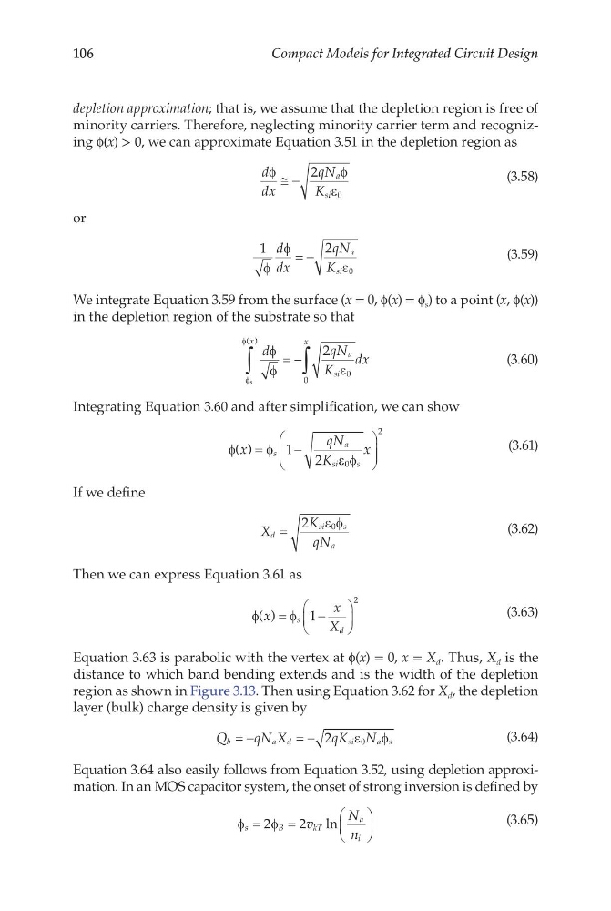
minority carriers. Therefore, neglecting minority carrier term and recognizing f(x) > 0, we can approximate Equation 3.51 in the depletion region as
d
dx
qN
K
a
si
φ
φ
ε
≅ −
2
0
(3.58)
or
1
2
0
φ
φ
ε
d
dx
qN
K
a
si
= −
(3.59)
We integrate Equation 3.59 from the surface (x = 0, f(x) = f s ) to a point (x, f(x))
in the depletion region of the substrate so that
d
qN
K
dx
x
a
si
x
φ
φ
ε
φ
φ
s
( )
∫
∫
= −
2
0
0
(3.60)
Integrating Equation 3.60 and after simplification, we can show
φ
φ
ε φ
( )
x
qN
K
x
s
a
si
s
=
−
1
2
0
2
(3.61)
If we define
X
K
qN
d
si
s
a
=
2
0
ε φ
(3.62)
Then we can express Equation 3.61 as
φ
φ
( )
x
x
X
s
d
=
−
1
2
(3.63)
Equation 3.63 is parabolic with the vertex at f(x) = 0, x = X d . Thus, X d is the
distance to which band bending extends and is the width of the depletion
region as shown in Figure 3.13. Then using Equation 3.62 for X d , the depletion
layer (bulk) charge density is given by
Q
qN X
qK N
b
a d
s i
a s
= −
= − 2
0
ε
φ
(3.64)
Equation 3.64 also easily follows from Equation 3.52, using depletion approximation. In an MOS capacitor system, the onset of strong inversion is defined by
φ
φ
s
B
kT
a
i
v
N
n
=
=
2
2 ln
(3.65)
Compact Models for Integrated Circuit Design
depletion approximation; that is, we assume that the depletion region is free of
minority carriers. Therefore, neglecting minority carrier term and recognizing f(x) > 0, we can approximate Equation 3.51 in the depletion region as
d
dx
qN
K
a
si
φ
φ
ε
≅ −
2
0
(3.58)
or
1
2
0
φ
φ
ε
d
dx
qN
K
a
si
= −
(3.59)
We integrate Equation 3.59 from the surface (x = 0, f(x) = f s ) to a point (x, f(x))
in the depletion region of the substrate so that
d
qN
K
dx
x
a
si
x
φ
φ
ε
φ
φ
s
( )
∫
∫
= −
2
0
0
(3.60)
Integrating Equation 3.60 and after simplification, we can show
φ
φ
ε φ
( )
x
qN
K
x
s
a
si
s
=
−
1
2
0
2
(3.61)
If we define
X
K
qN
d
si
s
a
=
2
0
ε φ
(3.62)
Then we can express Equation 3.61 as
φ
φ
( )
x
x
X
s
d
=
−
1
2
(3.63)
Equation 3.63 is parabolic with the vertex at f(x) = 0, x = X d . Thus, X d is the
distance to which band bending extends and is the width of the depletion
region as shown in Figure 3.13. Then using Equation 3.62 for X d , the depletion
layer (bulk) charge density is given by
Q
qN X
qK N
b
a d
s i
a s
= −
= − 2
0
ε
φ
(3.64)
Equation 3.64 also easily follows from Equation 3.52, using depletion approximation. In an MOS capacitor system, the onset of strong inversion is defined by
φ
φ
s
B
kT
a
i
v
N
n
=
=
2
2 ln
(3.65)