

78
Digital Electronics
A
B
Y1
Y
(a)
Y1
Y2
Y
A
B
C
D
(b)
C
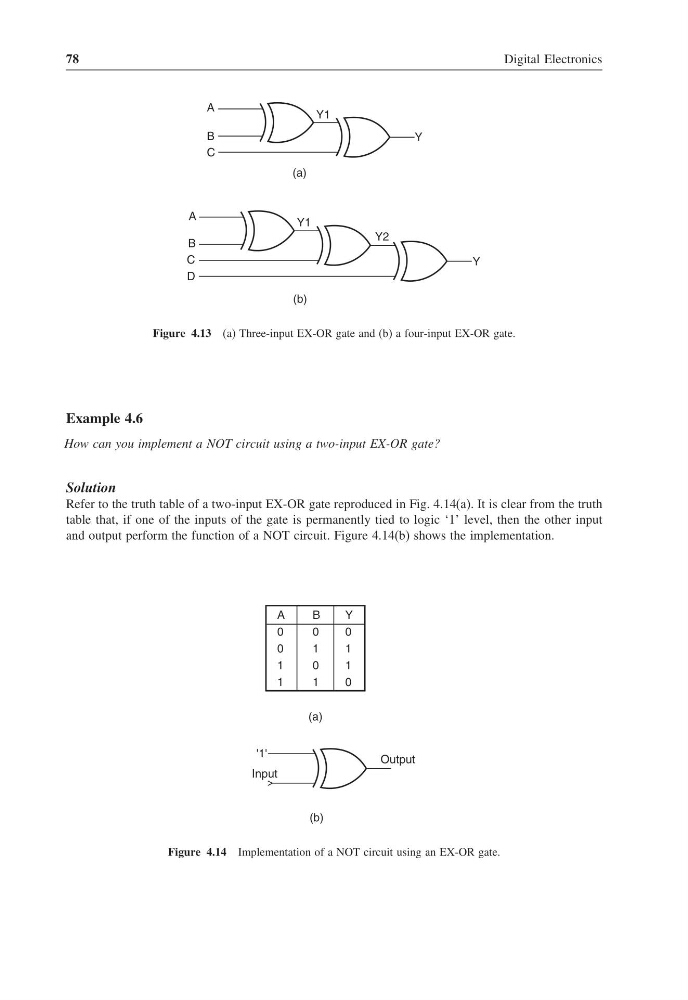
Figure 4.13 (a) Three-input EX-OR gate and (b) a four-input EX-OR gate.
Example 4.6
How can you implement a NOT circuit using a two-input EX-OR gate?
Solution
Refer to the truth table of a two-input EX-OR gate reproduced in Fig. 4.14(a). It is clear from the truth
table that, if one of the inputs of the gate is permanently tied to logic ‘1’ level, then the other input
and output perform the function of a NOT circuit. Figure 4.14(b) shows the implementation.
Output
Input
'1'
(b)
A
0
0
1
1
B
0
1
0
1
Y
0
1
1
0
(a)
Figure 4.14 Implementation of a NOT circuit using an EX-OR gate.
Digital Electronics
A
B
Y1
Y
(a)
Y1
Y2
Y
A
B
C
D
(b)
C
Figure 4.13 (a) Three-input EX-OR gate and (b) a four-input EX-OR gate.
Example 4.6
How can you implement a NOT circuit using a two-input EX-OR gate?
Solution
Refer to the truth table of a two-input EX-OR gate reproduced in Fig. 4.14(a). It is clear from the truth
table that, if one of the inputs of the gate is permanently tied to logic ‘1’ level, then the other input
and output perform the function of a NOT circuit. Figure 4.14(b) shows the implementation.
Output
Input
'1'
(b)
A
0
0
1
1
B
0
1
0
1
Y
0
1
1
0
(a)
Figure 4.14 Implementation of a NOT circuit using an EX-OR gate.