

Logic Gates and Related Devices
77
A
B
Y=A B
+
A
0
0
1
1
B
0
1
0
1
Y
0
1
1
0
(a)
(b)
A
0
0
0
0
0
0
0
0
1
1
1
1
1
1
1
1
B
0
0
0
0
1
1
1
1
0
0
0
0
1
1
1
1
C
0
0
1
1
0
0
1
1
0
0
1
1
0
0
1
1
D
0
1
0
1
0
1
0
1
0
1
0
1
0
1
0
1
Y
0
1
1
0
1
0
0
1
1
0
0
1
0
1
1
0
(c)
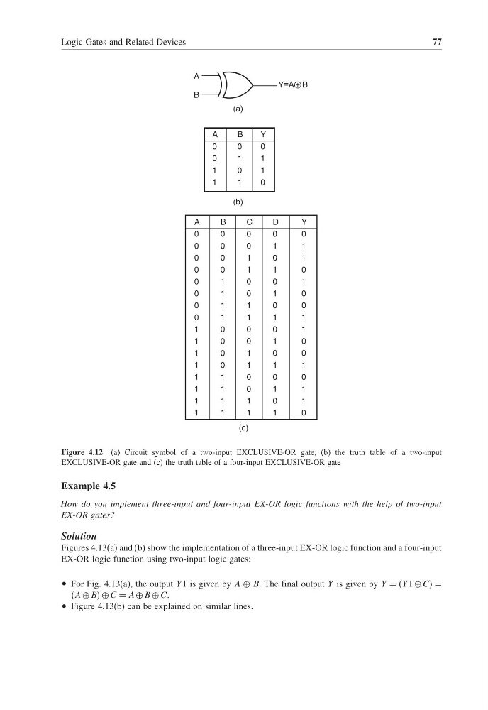
Figure 4.12 (a) Circuit symbol of a two-input EXCLUSIVE-OR gate, (b) the truth table of a two-input
EXCLUSIVE-OR gate and (c) the truth table of a four-input EXCLUSIVE-OR gate
Example 4.5
How do you implement three-input and four-input EX-OR logic functions with the help of two-input
EX-OR gates?
Solution
Figures 4.13(a) and (b) show the implementation of a three-input EX-OR logic function and a four-input
EX-OR logic function using two-input logic gates:
• For Fig. 4.13(a), the output Y 1 is given by A ⊕ B. The final output Y is given by Y = Y 1 ⊕ CC =
A ⊕ BB ⊕ C = A ⊕ B ⊕ C.
• Figure 4.13(b) can be explained on similar lines.
77
A
B
Y=A B
+
A
0
0
1
1
B
0
1
0
1
Y
0
1
1
0
(a)
(b)
A
0
0
0
0
0
0
0
0
1
1
1
1
1
1
1
1
B
0
0
0
0
1
1
1
1
0
0
0
0
1
1
1
1
C
0
0
1
1
0
0
1
1
0
0
1
1
0
0
1
1
D
0
1
0
1
0
1
0
1
0
1
0
1
0
1
0
1
Y
0
1
1
0
1
0
0
1
1
0
0
1
0
1
1
0
(c)
Figure 4.12 (a) Circuit symbol of a two-input EXCLUSIVE-OR gate, (b) the truth table of a two-input
EXCLUSIVE-OR gate and (c) the truth table of a four-input EXCLUSIVE-OR gate
Example 4.5
How do you implement three-input and four-input EX-OR logic functions with the help of two-input
EX-OR gates?
Solution
Figures 4.13(a) and (b) show the implementation of a three-input EX-OR logic function and a four-input
EX-OR logic function using two-input logic gates:
• For Fig. 4.13(a), the output Y 1 is given by A ⊕ B. The final output Y is given by Y = Y 1 ⊕ CC =
A ⊕ BB ⊕ C = A ⊕ B ⊕ C.
• Figure 4.13(b) can be explained on similar lines.