

76
Digital Electronics
Y=X
X
X
(a)
X
0
1
Y
1
0
(b)
Y=X
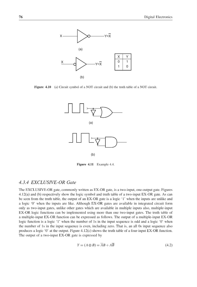
Figure 4.10 (a) Circuit symbol of a NOT circuit and (b) the truth table of a NOT circuit.
(a)
(b)
Figure 4.11 Example 4.4.
4.3.4 EXCLUSIVE-OR Gate
The EXCLUSIVE-OR gate, commonly written as EX-OR gate, is a two-input, one-output gate. Figures
4.12(a) and (b) respectively show the logic symbol and truth table of a two-input EX-OR gate. As can
be seen from the truth table, the output of an EX-OR gate is a logic ‘1’ when the inputs are unlike and
a logic ‘0’ when the inputs are like. Although EX-OR gates are available in integrated circuit form
only as two-input gates, unlike other gates which are available in multiple inputs also, multiple-input
EX-OR logic functions can be implemented using more than one two-input gates. The truth table of
a multiple-input EX-OR function can be expressed as follows. The output of a multiple-input EX-OR
logic function is a logic ‘1’ when the number of 1s in the input sequence is odd and a logic ‘0’ when
the number of 1s in the input sequence is even, including zero. That is, an all 0s input sequence also
produces a logic ‘0’ at the output. Figure 4.12(c) shows the truth table of a four-input EX-OR function.
The output of a two-input EX-OR gate is expressed by
Y = A ⊕ BB = AB + AB
(4.2)
Digital Electronics
Y=X
X
X
(a)
X
0
1
Y
1
0
(b)
Y=X
Figure 4.10 (a) Circuit symbol of a NOT circuit and (b) the truth table of a NOT circuit.
(a)
(b)
Figure 4.11 Example 4.4.
4.3.4 EXCLUSIVE-OR Gate
The EXCLUSIVE-OR gate, commonly written as EX-OR gate, is a two-input, one-output gate. Figures
4.12(a) and (b) respectively show the logic symbol and truth table of a two-input EX-OR gate. As can
be seen from the truth table, the output of an EX-OR gate is a logic ‘1’ when the inputs are unlike and
a logic ‘0’ when the inputs are like. Although EX-OR gates are available in integrated circuit form
only as two-input gates, unlike other gates which are available in multiple inputs also, multiple-input
EX-OR logic functions can be implemented using more than one two-input gates. The truth table of
a multiple-input EX-OR function can be expressed as follows. The output of a multiple-input EX-OR
logic function is a logic ‘1’ when the number of 1s in the input sequence is odd and a logic ‘0’ when
the number of 1s in the input sequence is even, including zero. That is, an all 0s input sequence also
produces a logic ‘0’ at the output. Figure 4.12(c) shows the truth table of a four-input EX-OR function.
The output of a two-input EX-OR gate is expressed by
Y = A ⊕ BB = AB + AB
(4.2)