

Logic Gates and Related Devices
73
OR gate produces the output Y 2 = Y 1 + CC = A + B + CC. Similarly, the output of OR gate 3 is
Y 3 = Y 2 + DD = A + B + C + DD. In the case of Fig. 4.5(b), the output of OR gate 1 is Y 1 = A + BB.
The second OR gate produces the output Y 2 = C + DD. Output Y 3 of the third OR gate is given by
Y 1 + Y 2 = A + B + C + DD.
Example 4.2
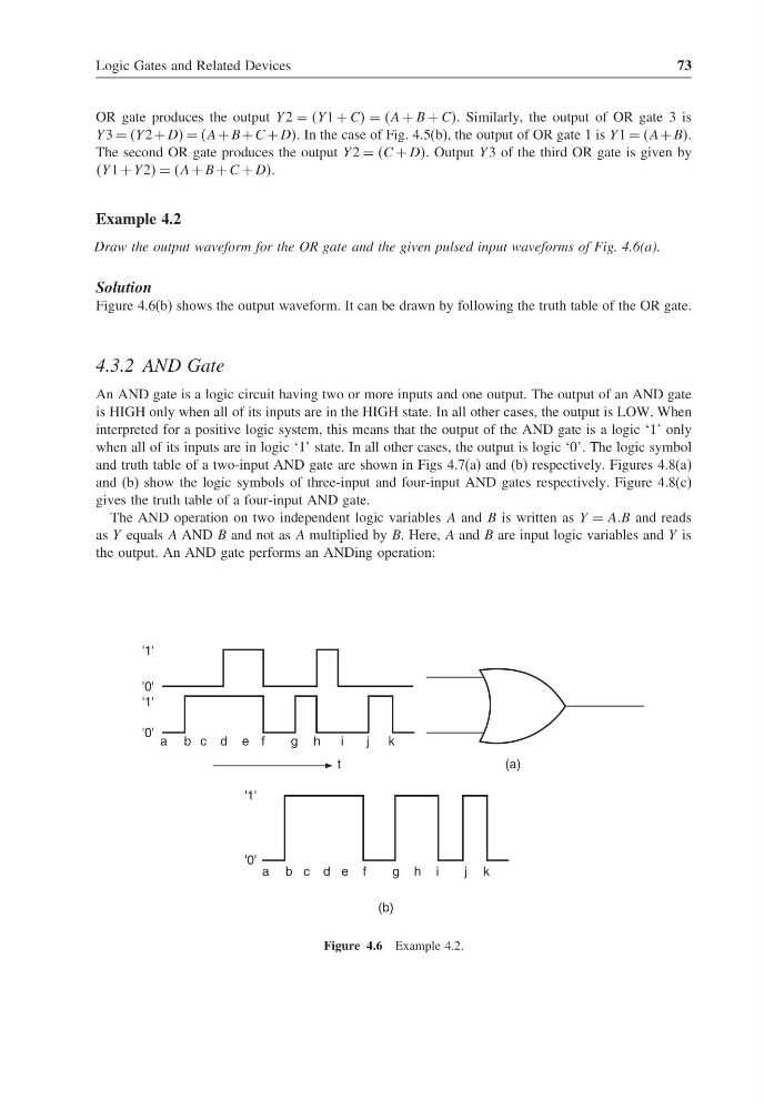
Draw the output waveform for the OR gate and the given pulsed input waveforms of Fig. 4.6(a).
Solution
Figure 4.6(b) shows the output waveform. It can be drawn by following the truth table of the OR gate.
4.3.2 AND Gate
An AND gate is a logic circuit having two or more inputs and one output. The output of an AND gate
is HIGH only when all of its inputs are in the HIGH state. In all other cases, the output is LOW. When
interpreted for a positive logic system, this means that the output of the AND gate is a logic ‘1’ only
when all of its inputs are in logic ‘1’ state. In all other cases, the output is logic ‘0’. The logic symbol
and truth table of a two-input AND gate are shown in Figs 4.7(a) and (b) respectively. Figures 4.8(a)
and (b) show the logic symbols of three-input and four-input AND gates respectively. Figure 4.8(c)
gives the truth table of a four-input AND gate.
The AND operation on two independent logic variables A and B is written as Y = AAB and reads
as Y equals A AND B and not as A multiplied by B. Here, A and B are input logic variables and Y is
the output. An AND gate performs an ANDing operation:
a b c d e f
g h
i
j k
'1'
'0'
'1'
'0'
(a)
t
a b c d e f
g h i
j k
(b)
'1'
'0'
Figure 4.6 Example 4.2.
73
OR gate produces the output Y 2 = Y 1 + CC = A + B + CC. Similarly, the output of OR gate 3 is
Y 3 = Y 2 + DD = A + B + C + DD. In the case of Fig. 4.5(b), the output of OR gate 1 is Y 1 = A + BB.
The second OR gate produces the output Y 2 = C + DD. Output Y 3 of the third OR gate is given by
Y 1 + Y 2 = A + B + C + DD.
Example 4.2
Draw the output waveform for the OR gate and the given pulsed input waveforms of Fig. 4.6(a).
Solution
Figure 4.6(b) shows the output waveform. It can be drawn by following the truth table of the OR gate.
4.3.2 AND Gate
An AND gate is a logic circuit having two or more inputs and one output. The output of an AND gate
is HIGH only when all of its inputs are in the HIGH state. In all other cases, the output is LOW. When
interpreted for a positive logic system, this means that the output of the AND gate is a logic ‘1’ only
when all of its inputs are in logic ‘1’ state. In all other cases, the output is logic ‘0’. The logic symbol
and truth table of a two-input AND gate are shown in Figs 4.7(a) and (b) respectively. Figures 4.8(a)
and (b) show the logic symbols of three-input and four-input AND gates respectively. Figure 4.8(c)
gives the truth table of a four-input AND gate.
The AND operation on two independent logic variables A and B is written as Y = AAB and reads
as Y equals A AND B and not as A multiplied by B. Here, A and B are input logic variables and Y is
the output. An AND gate performs an ANDing operation:
a b c d e f
g h
i
j k
'1'
'0'
'1'
'0'
(a)
t
a b c d e f
g h i
j k
(b)
'1'
'0'
Figure 4.6 Example 4.2.