

72
Digital Electronics
Y=A+B+C
A
B
C
(a)
Y=A+B+C+D
A
C
(b)
D
A
0
0
0
0
1
1
1
1
B
0
0
1
1
0
0
1
1
C
0
1
0
1
0
1
0
1
Y
0
1
1
1
1
1
1
1
(c)
B
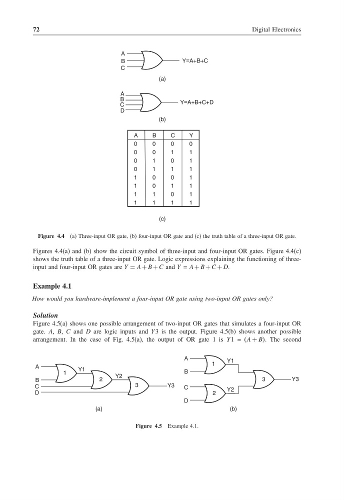
Figure 4.4 (a) Three-input OR gate, (b) four-input OR gate and (c) the truth table of a three-input OR gate.
Figures 4.4(a) and (b) show the circuit symbol of three-input and four-input OR gates. Figure 4.4(c)
shows the truth table of a three-input OR gate. Logic expressions explaining the functioning of threeinput and four-input OR gates are Y = A + B + C and Y = A + B + C + D.
Example 4.1
How would you hardware-implement a four-input OR gate using two-input OR gates only?
Solution
Figure 4.5(a) shows one possible arrangement of two-input OR gates that simulates a four-input OR
gate. A, B, C and D are logic inputs and Y 3 is the output. Figure 4.5(b) shows another possible
arrangement. In the case of Fig. 4.5(a), the output of OR gate 1 is Y 1 = (A + BB. The second
Y1
A
B
C
D
1
2
Y2
3
Y3
(a)
Y1
Y2
Y3
A
B
C
D
(b)
3
1
2
Figure 4.5 Example 4.1.
Digital Electronics
Y=A+B+C
A
B
C
(a)
Y=A+B+C+D
A
C
(b)
D
A
0
0
0
0
1
1
1
1
B
0
0
1
1
0
0
1
1
C
0
1
0
1
0
1
0
1
Y
0
1
1
1
1
1
1
1
(c)
B
Figure 4.4 (a) Three-input OR gate, (b) four-input OR gate and (c) the truth table of a three-input OR gate.
Figures 4.4(a) and (b) show the circuit symbol of three-input and four-input OR gates. Figure 4.4(c)
shows the truth table of a three-input OR gate. Logic expressions explaining the functioning of threeinput and four-input OR gates are Y = A + B + C and Y = A + B + C + D.
Example 4.1
How would you hardware-implement a four-input OR gate using two-input OR gates only?
Solution
Figure 4.5(a) shows one possible arrangement of two-input OR gates that simulates a four-input OR
gate. A, B, C and D are logic inputs and Y 3 is the output. Figure 4.5(b) shows another possible
arrangement. In the case of Fig. 4.5(a), the output of OR gate 1 is Y 1 = (A + BB. The second
Y1
A
B
C
D
1
2
Y2
3
Y3
(a)
Y1
Y2
Y3
A
B
C
D
(b)
3
1
2
Figure 4.5 Example 4.1.