

Logic Gates and Related Devices
71
A
0
0
0
0
1
1
1
1
B
0
0
1
1
0
0
1
1
C
0
1
0
1
0
1
0
1
Y
0
0
0
0
0
0
0
1
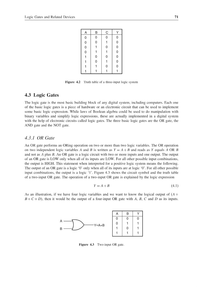
Figure 4.2 Truth table of a three-input logic system
4.3 Logic Gates
The logic gate is the most basic building block of any digital system, including computers. Each one
of the basic logic gates is a piece of hardware or an electronic circuit that can be used to implement
some basic logic expression. While laws of Boolean algebra could be used to do manipulation with
binary variables and simplify logic expressions, these are actually implemented in a digital system
with the help of electronic circuits called logic gates. The three basic logic gates are the OR gate, the
AND gate and the NOT gate.
4.3.1 OR Gate
An OR gate performs an ORing operation on two or more than two logic variables. The OR operation
on two independent logic variables A and B is written as Y = A + B and reads as Y equals A OR B
and not as A plus B. An OR gate is a logic circuit with two or more inputs and one output. The output
of an OR gate is LOW only when all of its inputs are LOW. For all other possible input combinations,
the output is HIGH. This statement when interpreted for a positive logic system means the following.
The output of an OR gate is a logic ‘0’ only when all of its inputs are at logic ‘0’. For all other possible
input combinations, the output is a logic ‘1’. Figure 4.3 shows the circuit symbol and the truth table
of a two-input OR gate. The operation of a two-input OR gate is explained by the logic expression
Y = A + B
(4.1)
As an illustration, if we have four logic variables and we want to know the logical output of (A +
B + C + DD, then it would be the output of a four-input OR gate with A, B, C and D as its inputs.
Y=A+B
A
B
A
0
0
1
1
B
0
1
0
1
Y
0
1
1
1
Figure 4.3 Two-input OR gate.
71
A
0
0
0
0
1
1
1
1
B
0
0
1
1
0
0
1
1
C
0
1
0
1
0
1
0
1
Y
0
0
0
0
0
0
0
1
Figure 4.2 Truth table of a three-input logic system
4.3 Logic Gates
The logic gate is the most basic building block of any digital system, including computers. Each one
of the basic logic gates is a piece of hardware or an electronic circuit that can be used to implement
some basic logic expression. While laws of Boolean algebra could be used to do manipulation with
binary variables and simplify logic expressions, these are actually implemented in a digital system
with the help of electronic circuits called logic gates. The three basic logic gates are the OR gate, the
AND gate and the NOT gate.
4.3.1 OR Gate
An OR gate performs an ORing operation on two or more than two logic variables. The OR operation
on two independent logic variables A and B is written as Y = A + B and reads as Y equals A OR B
and not as A plus B. An OR gate is a logic circuit with two or more inputs and one output. The output
of an OR gate is LOW only when all of its inputs are LOW. For all other possible input combinations,
the output is HIGH. This statement when interpreted for a positive logic system means the following.
The output of an OR gate is a logic ‘0’ only when all of its inputs are at logic ‘0’. For all other possible
input combinations, the output is a logic ‘1’. Figure 4.3 shows the circuit symbol and the truth table
of a two-input OR gate. The operation of a two-input OR gate is explained by the logic expression
Y = A + B
(4.1)
As an illustration, if we have four logic variables and we want to know the logical output of (A +
B + C + DD, then it would be the output of a four-input OR gate with A, B, C and D as its inputs.
Y=A+B
A
B
A
0
0
1
1
B
0
1
0
1
Y
0
1
1
1
Figure 4.3 Two-input OR gate.