

582
Digital Electronics
1
24
T2/P1.0
T2EX/P1.1
P1.2
P1.3
P1.4
P1.5
P1.6
P1.7
RST
RxD/P3.0
TxD/P3.1
INT0/P3.2
INT1/P3.3
T0/P3.4
T1/P3.5
WR/P3.6
RD/3.7
XTAL2
XTAL1
V SS
1
2
3
4
5
6
7
8
9
10
11
12
13
14
15
16
17
18
19
20
40
39
38
37
36
35
34
33
32
31
30
29
28
27
26
25
24
23
22
21
V
P0.0/AD0
EA/V
ALE
PSEN
P2.7/A15
CC
PP
P0.1/AD1
P0.2/AD2
P0.3/AD3
P0.4/AD4
P0.5/AD5
P0.6/AD6
P0.7/AD7
P2.6/A14
P2.5/A13
P2.4/A12
P2.3/A11
P2.2/A10
P2.1/A9
P2.0/A8
DUAL
IN LINE
PACKAGE
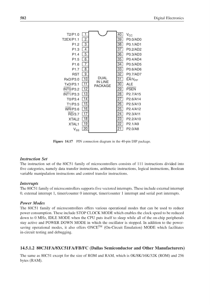
Figure 14.17 PIN connection diagram in the 40-pin DIP package.
Instruction Set
The instruction set of the 80C51 family of microcontrollers consists of 111 instructions divided into
five categories, namely data transfer instructions, arithmetic instructions, logical instructions, Boolean
variable manipulation instructions and control transfer instructions.
Interrupts
The 80C51 family of microcontrollers supports five vectored interrupts. These include external interrupt
0, external interrupt 1, timer/counter 0 interrupt, timer/counter 1 interrupt and serial port interrupts.
Power Modes
The 80C51 family of microcontrollers offers various operational modes that can be used to reduce
power consumption. These include STOP CLOCK MODE which enables the clock speed to be reduced
down to 0 MHz, IDLE MODE when the CPU puts itself to sleep while all of the on-chip peripherals
stay active and POWER DOWN MODE in which the oscillator is stopped. In addition to the powersaving operational modes, it also offers ONCE
TM (On-Circuit Emulation) MODE which facilitates
in-circuit testing and debugging.
14.5.1.2 80C31FA/8XC51FA/FB/FC (Dallas Semiconductor and Other Manufacturers)
The same as 80C51 except for the size of ROM and RAM, which is 0K/8K/16K/32K (ROM) and 256
bytes (RAM).
Digital Electronics
1
24
T2/P1.0
T2EX/P1.1
P1.2
P1.3
P1.4
P1.5
P1.6
P1.7
RST
RxD/P3.0
TxD/P3.1
INT0/P3.2
INT1/P3.3
T0/P3.4
T1/P3.5
WR/P3.6
RD/3.7
XTAL2
XTAL1
V SS
1
2
3
4
5
6
7
8
9
10
11
12
13
14
15
16
17
18
19
20
40
39
38
37
36
35
34
33
32
31
30
29
28
27
26
25
24
23
22
21
V
P0.0/AD0
EA/V
ALE
PSEN
P2.7/A15
CC
PP
P0.1/AD1
P0.2/AD2
P0.3/AD3
P0.4/AD4
P0.5/AD5
P0.6/AD6
P0.7/AD7
P2.6/A14
P2.5/A13
P2.4/A12
P2.3/A11
P2.2/A10
P2.1/A9
P2.0/A8
DUAL
IN LINE
PACKAGE
Figure 14.17 PIN connection diagram in the 40-pin DIP package.
Instruction Set
The instruction set of the 80C51 family of microcontrollers consists of 111 instructions divided into
five categories, namely data transfer instructions, arithmetic instructions, logical instructions, Boolean
variable manipulation instructions and control transfer instructions.
Interrupts
The 80C51 family of microcontrollers supports five vectored interrupts. These include external interrupt
0, external interrupt 1, timer/counter 0 interrupt, timer/counter 1 interrupt and serial port interrupts.
Power Modes
The 80C51 family of microcontrollers offers various operational modes that can be used to reduce
power consumption. These include STOP CLOCK MODE which enables the clock speed to be reduced
down to 0 MHz, IDLE MODE when the CPU puts itself to sleep while all of the on-chip peripherals
stay active and POWER DOWN MODE in which the oscillator is stopped. In addition to the powersaving operational modes, it also offers ONCE
TM (On-Circuit Emulation) MODE which facilitates
in-circuit testing and debugging.
14.5.1.2 80C31FA/8XC51FA/FB/FC (Dallas Semiconductor and Other Manufacturers)
The same as 80C51 except for the size of ROM and RAM, which is 0K/8K/16K/32K (ROM) and 256
bytes (RAM).