

572
Digital Electronics
are embedded in each data byte. Compared with the synchronous communication interface, it offers
lower data transmission rates. It is also referred to as the universal asynchronous receiver/transmitter
(UART) or the serial communication interface (SCI). The synchronous communication interface uses
a synchronized clock to transmit and receive each bit. Synchronization of transmitter and receiver
clocks is usually accomplished by using an additional clock line linking the transmitter and the
receiver. It is not recommended for long distance communication. It is also referred to as the serial
peripheral interface (SPI). Microcontroller 68HC11 offers an asynchronous non-return-to-zero serial
communication interface and also a synchronous serial peripheral interface. The 80C51 family of
microcontrollers offers a full duplex-enhanced UART interface.
Since a large number of peripheral devices are equipped to communicate with an RS-232-compatible
interface, which is a serial interface standard that specifies the different aspects, including electrical,
mechanical, functional and procedural specifications, a variety of chips are available to translate
microcontroller signals to RS-232-compatible signals. These chips are equipped to provide interfacing
for a two-way communication system.
14.2.5.5 Interintegrated Circuit (I
2 C) Bus
The interintegrated circuit (I
2 C) bus is a two-wire, low- to-medium-speed serial communication
interface developed by Philips Semiconductors in the early 1980s for chip-to-chip communications.
The two wires in the I
2 C bus are called clock (SCL) and data (SDA). The SDA wire carries data, while
the SCL wire synchronizes the transmitter and receiver during data transfer.
It is a proven industry-standard communication protocol used in a variety of electronic products,
which is particularly facilitated by its low cost and powerful features. It is supported by a large number
of semiconductor and system manufacturers who offer a variety of electronic products including input
and output devices, different types of sensor, memory devices, displays, data entry devices, etc. Some
of the important features offered by I
2 C devices are briefly described in the following paragraphs.
I
2 C devices offer master–slave hierarchy. These are classified as either master (the device that initiates
the message) or slave (the device that responds to the message). The device can be either master only or
slave only or can be switched between master and slave depending upon the application requirement.
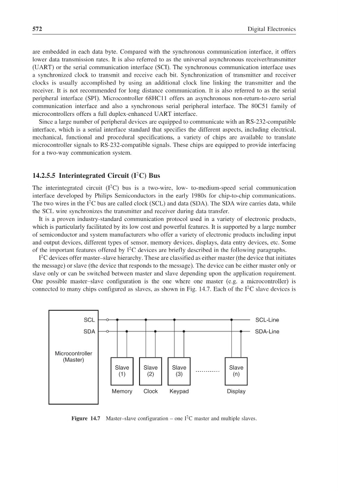
One possible master–slave configuration is the one where one master (e.g. a microcontroller) is
connected to many chips configured as slaves, as shown in Fig. 14.7. Each of the I
2 C slave devices is
Microcontroller
(Master)
SCL
Slave
(1)
SDA
Slave
(2)
Slave
(3)
Slave
(n)
Memory
Clock
Keypad
Display
SCL-Line
SDA-Line
Figure 14.7 Master–slave configuration – one I
2 C master and multiple slaves.
Digital Electronics
are embedded in each data byte. Compared with the synchronous communication interface, it offers
lower data transmission rates. It is also referred to as the universal asynchronous receiver/transmitter
(UART) or the serial communication interface (SCI). The synchronous communication interface uses
a synchronized clock to transmit and receive each bit. Synchronization of transmitter and receiver
clocks is usually accomplished by using an additional clock line linking the transmitter and the
receiver. It is not recommended for long distance communication. It is also referred to as the serial
peripheral interface (SPI). Microcontroller 68HC11 offers an asynchronous non-return-to-zero serial
communication interface and also a synchronous serial peripheral interface. The 80C51 family of
microcontrollers offers a full duplex-enhanced UART interface.
Since a large number of peripheral devices are equipped to communicate with an RS-232-compatible
interface, which is a serial interface standard that specifies the different aspects, including electrical,
mechanical, functional and procedural specifications, a variety of chips are available to translate
microcontroller signals to RS-232-compatible signals. These chips are equipped to provide interfacing
for a two-way communication system.
14.2.5.5 Interintegrated Circuit (I
2 C) Bus
The interintegrated circuit (I
2 C) bus is a two-wire, low- to-medium-speed serial communication
interface developed by Philips Semiconductors in the early 1980s for chip-to-chip communications.
The two wires in the I
2 C bus are called clock (SCL) and data (SDA). The SDA wire carries data, while
the SCL wire synchronizes the transmitter and receiver during data transfer.
It is a proven industry-standard communication protocol used in a variety of electronic products,
which is particularly facilitated by its low cost and powerful features. It is supported by a large number
of semiconductor and system manufacturers who offer a variety of electronic products including input
and output devices, different types of sensor, memory devices, displays, data entry devices, etc. Some
of the important features offered by I
2 C devices are briefly described in the following paragraphs.
I
2 C devices offer master–slave hierarchy. These are classified as either master (the device that initiates
the message) or slave (the device that responds to the message). The device can be either master only or
slave only or can be switched between master and slave depending upon the application requirement.
One possible master–slave configuration is the one where one master (e.g. a microcontroller) is
connected to many chips configured as slaves, as shown in Fig. 14.7. Each of the I
2 C slave devices is
Microcontroller
(Master)
SCL
Slave
(1)
SDA
Slave
(2)
Slave
(3)
Slave
(n)
Memory
Clock
Keypad
Display
SCL-Line
SDA-Line
Figure 14.7 Master–slave configuration – one I
2 C master and multiple slaves.