

Microcontrollers
571
Special
Storage
Regsister
Free-Running
Counter
Programmed
Event
I/O
Pin
Timer Input
Flag
Timer Input
Interrupt
System
Input
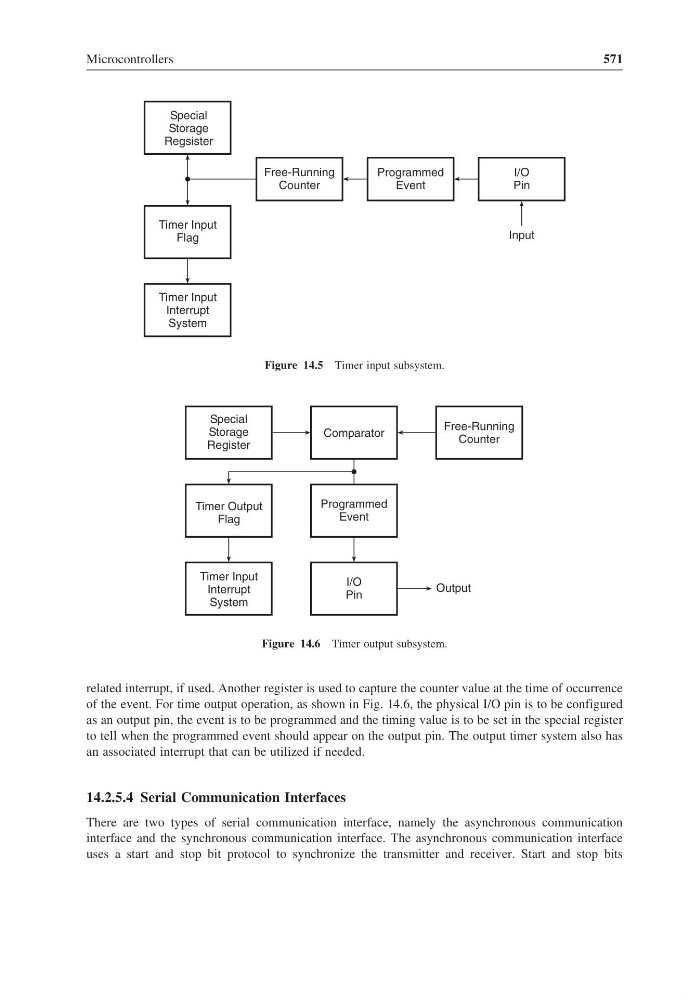
Figure 14.5 Timer input subsystem.
Special
Storage
Register
Timer Output
Flag
Timer Input
Interrupt
System
Comparator
Programmed
Event
I/O
Pin
Output
Free-Running
Counter
Figure 14.6 Timer output subsystem.
related interrupt, if used. Another register is used to capture the counter value at the time of occurrence
of the event. For time output operation, as shown in Fig. 14.6, the physical I/O pin is to be configured
as an output pin, the event is to be programmed and the timing value is to be set in the special register
to tell when the programmed event should appear on the output pin. The output timer system also has
an associated interrupt that can be utilized if needed.
14.2.5.4 Serial Communication Interfaces
There are two types of serial communication interface, namely the asynchronous communication
interface and the synchronous communication interface. The asynchronous communication interface
uses a start and stop bit protocol to synchronize the transmitter and receiver. Start and stop bits
571
Special
Storage
Regsister
Free-Running
Counter
Programmed
Event
I/O
Pin
Timer Input
Flag
Timer Input
Interrupt
System
Input
Figure 14.5 Timer input subsystem.
Special
Storage
Register
Timer Output
Flag
Timer Input
Interrupt
System
Comparator
Programmed
Event
I/O
Pin
Output
Free-Running
Counter
Figure 14.6 Timer output subsystem.
related interrupt, if used. Another register is used to capture the counter value at the time of occurrence
of the event. For time output operation, as shown in Fig. 14.6, the physical I/O pin is to be configured
as an output pin, the event is to be programmed and the timing value is to be set in the special register
to tell when the programmed event should appear on the output pin. The output timer system also has
an associated interrupt that can be utilized if needed.
14.2.5.4 Serial Communication Interfaces
There are two types of serial communication interface, namely the asynchronous communication
interface and the synchronous communication interface. The asynchronous communication interface
uses a start and stop bit protocol to synchronize the transmitter and receiver. Start and stop bits