

542
Digital Electronics
1
24
V cc
HOLD
HLDA
CLK(OUT)
RESET IN
READY
10/M
S 1
RD
WR
ALE
S 0
A 15
A 14
A 13
A 12
A 11
A 10
A 9
A 8
X 1
X 2
RESET OUT
SOD
SID
TRAP
RST 7.5
RST 6.5
RST 5.5
INTR
INTA
AD 0
AD 1
AD 2
AD 3
AD 4
AD 5
AD 6
AD 7
GND
1
2
3
4
5
6
7
8
9
10
11
12
13
14
15
16
17
18
19
20
40
39
38
37
36
35
34
33
32
31
30
29
28
27
26
25
24
23
22
21
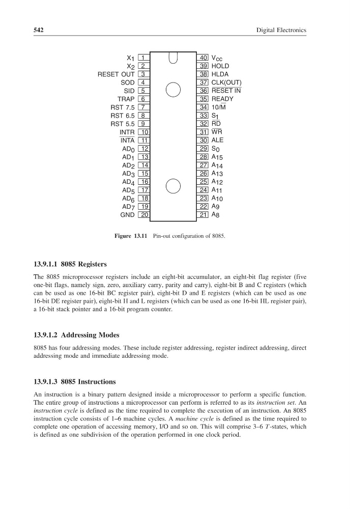
Figure 13.11 Pin-out configuration of 8085.
13.9.1.1 8085 Registers
The 8085 microprocessor registers include an eight-bit accumulator, an eight-bit flag register (five
one-bit flags, namely sign, zero, auxiliary carry, parity and carry), eight-bit B and C registers (which
can be used as one 16-bit BC register pair), eight-bit D and E registers (which can be used as one
16-bit DE register pair), eight-bit H and L registers (which can be used as one 16-bit HL register pair),
a 16-bit stack pointer and a 16-bit program counter.
13.9.1.2 Addressing Modes
8085 has four addressing modes. These include register addressing, register indirect addressing, direct
addressing mode and immediate addressing mode.
13.9.1.3 8085 Instructions
An instruction is a binary pattern designed inside a microprocessor to perform a specific function.
The entire group of instructions a microprocessor can perform is referred to as its instruction set. An
instruction cycle is defined as the time required to complete the execution of an instruction. An 8085
instruction cycle consists of 1–6 machine cycles. A machine cycle is defined as the time required to
complete one operation of accessing memory, I/O and so on. This will comprise 3–6 T -states, which
is defined as one subdivision of the operation performed in one clock period.
Digital Electronics
1
24
V cc
HOLD
HLDA
CLK(OUT)
RESET IN
READY
10/M
S 1
RD
WR
ALE
S 0
A 15
A 14
A 13
A 12
A 11
A 10
A 9
A 8
X 1
X 2
RESET OUT
SOD
SID
TRAP
RST 7.5
RST 6.5
RST 5.5
INTR
INTA
AD 0
AD 1
AD 2
AD 3
AD 4
AD 5
AD 6
AD 7
GND
1
2
3
4
5
6
7
8
9
10
11
12
13
14
15
16
17
18
19
20
40
39
38
37
36
35
34
33
32
31
30
29
28
27
26
25
24
23
22
21
Figure 13.11 Pin-out configuration of 8085.
13.9.1.1 8085 Registers
The 8085 microprocessor registers include an eight-bit accumulator, an eight-bit flag register (five
one-bit flags, namely sign, zero, auxiliary carry, parity and carry), eight-bit B and C registers (which
can be used as one 16-bit BC register pair), eight-bit D and E registers (which can be used as one
16-bit DE register pair), eight-bit H and L registers (which can be used as one 16-bit HL register pair),
a 16-bit stack pointer and a 16-bit program counter.
13.9.1.2 Addressing Modes
8085 has four addressing modes. These include register addressing, register indirect addressing, direct
addressing mode and immediate addressing mode.
13.9.1.3 8085 Instructions
An instruction is a binary pattern designed inside a microprocessor to perform a specific function.
The entire group of instructions a microprocessor can perform is referred to as its instruction set. An
instruction cycle is defined as the time required to complete the execution of an instruction. An 8085
instruction cycle consists of 1–6 machine cycles. A machine cycle is defined as the time required to
complete one operation of accessing memory, I/O and so on. This will comprise 3–6 T -states, which
is defined as one subdivision of the operation performed in one clock period.