

520
Digital Electronics
1
24
1
2
3
4
5
6
7
8
9
10
11
12
13
14
15
16
17
18
19
40
39
38
37
36
35
34
33
32
31
30
29
28
27
26
25
24
23
22
Intersil
7106
R 4
C 11
P 1
R 3
C 9
R 2
+
Input
C 8
C 7
R 1
C 10
20
21
Intersil
7106
+
-
9V
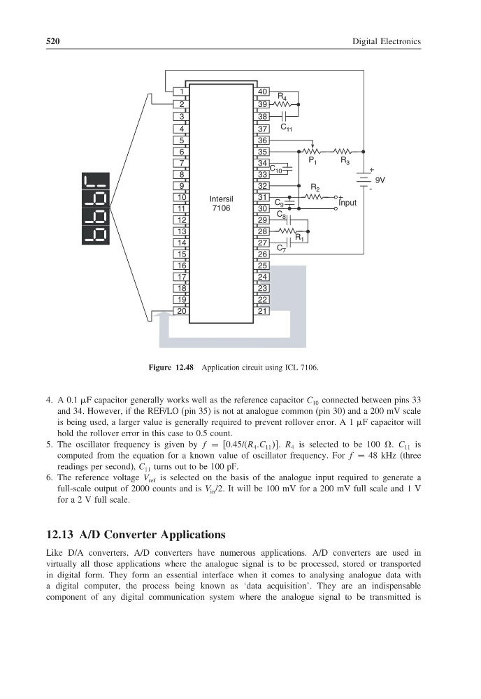
Figure 12.48 Application circuit using ICL 7106.
4. A 0.1 F capacitor generally works well as the reference capacitor C 10 connected between pins 33
and 34. However, if the REF/LO (pin 35) is not at analogue common (pin 30) and a 200 mV scale
is being used, a larger value is generally required to prevent rollover error. A 1 F capacitor will
hold the rollover error in this case to 0.5 count.
5. The oscillator frequency is given by f = [0.45/(R 4 .C 11 ]. R 4 is selected to be 100 . C 11 is
computed from the equation for a known value of oscillator frequency. For f = 48 kHz (three
readings per second), C 11 turns out to be 100 pF.
6. The reference voltage V ref is selected on the basis of the analogue input required to generate a
full-scale output of 2000 counts and is V in /2 It will be 100 mV for a 200 mV full scale and 1 V
for a 2 V full scale.
12.13 A/D Converter Applications
Like D/A converters, A/D converters have numerous applications. A/D converters are used in
virtually all those applications where the analogue signal is to be processed, stored or transported
in digital form. They form an essential interface when it comes to analysing analogue data with
a digital computer, the process being known as ‘data acquisition’. They are an indispensable
component of any digital communication system where the analogue signal to be transmitted is
Digital Electronics
1
24
1
2
3
4
5
6
7
8
9
10
11
12
13
14
15
16
17
18
19
40
39
38
37
36
35
34
33
32
31
30
29
28
27
26
25
24
23
22
Intersil
7106
R 4
C 11
P 1
R 3
C 9
R 2
+
Input
C 8
C 7
R 1
C 10
20
21
Intersil
7106
+
-
9V
Figure 12.48 Application circuit using ICL 7106.
4. A 0.1 F capacitor generally works well as the reference capacitor C 10 connected between pins 33
and 34. However, if the REF/LO (pin 35) is not at analogue common (pin 30) and a 200 mV scale
is being used, a larger value is generally required to prevent rollover error. A 1 F capacitor will
hold the rollover error in this case to 0.5 count.
5. The oscillator frequency is given by f = [0.45/(R 4 .C 11 ]. R 4 is selected to be 100 . C 11 is
computed from the equation for a known value of oscillator frequency. For f = 48 kHz (three
readings per second), C 11 turns out to be 100 pF.
6. The reference voltage V ref is selected on the basis of the analogue input required to generate a
full-scale output of 2000 counts and is V in /2 It will be 100 mV for a 200 mV full scale and 1 V
for a 2 V full scale.
12.13 A/D Converter Applications
Like D/A converters, A/D converters have numerous applications. A/D converters are used in
virtually all those applications where the analogue signal is to be processed, stored or transported
in digital form. They form an essential interface when it comes to analysing analogue data with
a digital computer, the process being known as ‘data acquisition’. They are an indispensable
component of any digital communication system where the analogue signal to be transmitted is