

Data Conversion Circuits – D/A and A/D Converters
517
Clock
SAR
23
20
27
32
6
8
19
DAC
16
24
REF
6.3K
5K
5K
14
25
12
17
13
11
15
26
22
7
21
9
10
+
−
Clock
Inhibit
LSB
MSB
Status
Serial Out
MSB
Digital
GND
Analog
GND
Comp IN
10V Span
Input
20V Span
Input
Ref
Out
Gain
ADJ
Clock
IN
Clock
Out
Comparator
18
+5V
Digital
Short
Cycle
+V S
1
−V S
Convert
Start
+5V
Analog
AD ADC80
Bipolar
Offset Out
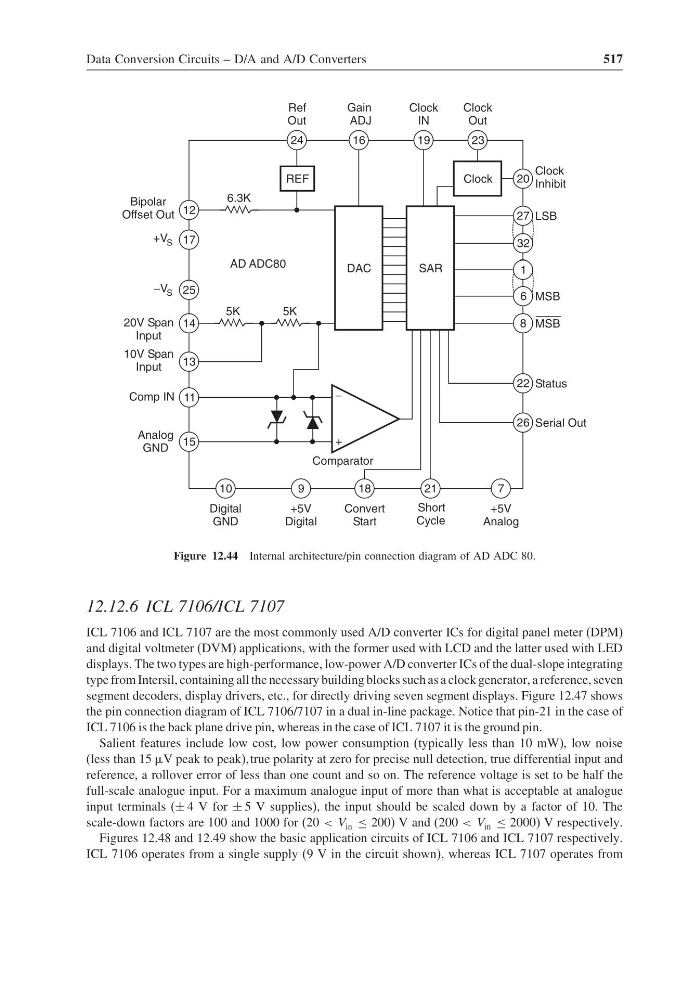
Figure 12.44 Internal architecture/pin connection diagram of AD ADC 80.
12.12.6 ICL 7106/ICL 7107
ICL 7106 and ICL 7107 are the most commonly used A/D converter ICs for digital panel meter (DPM)
and digital voltmeter (DVM) applications, with the former used with LCD and the latter used with LED
displays. The two types are high-performance, low-power A/D converter ICs of the dual-slope integrating
type from Intersil, containing all the necessary building blocks such as a clock generator, a reference, seven
segment decoders, display drivers, etc., for directly driving seven segment displays. Figure 12.47 shows
the pin connection diagram of ICL 7106/7107 in a dual in-line package. Notice that pin-21 in the case of
ICL 7106 is the back plane drive pin, whereas in the case of ICL 7107 it is the ground pin.
Salient features include low cost, low power consumption (typically less than 10 mW), low noise
(less than 15 V peak to peak)true polarity at zero for precise null detection, true differential input and
reference, a rollover error of less than one count and so on. The reference voltage is set to be half the
full-scale analogue input. For a maximum analogue input of more than what is acceptable at analogue
input terminals (± 4 V for ± 5 V supplies), the input should be scaled down by a factor of 10. The
scale-down factors are 100 and 1000 for (20 < V in ≤ 200) V and (200 < V in ≤ 2000) V respectively.
Figures 12.48 and 12.49 show the basic application circuits of ICL 7106 and ICL 7107 respectively.
ICL 7106 operates from a single supply (9 V in the circuit shown), whereas ICL 7107 operates from
517
Clock
SAR
23
20
27
32
6
8
19
DAC
16
24
REF
6.3K
5K
5K
14
25
12
17
13
11
15
26
22
7
21
9
10
+
−
Clock
Inhibit
LSB
MSB
Status
Serial Out
MSB
Digital
GND
Analog
GND
Comp IN
10V Span
Input
20V Span
Input
Ref
Out
Gain
ADJ
Clock
IN
Clock
Out
Comparator
18
+5V
Digital
Short
Cycle
+V S
1
−V S
Convert
Start
+5V
Analog
AD ADC80
Bipolar
Offset Out
Figure 12.44 Internal architecture/pin connection diagram of AD ADC 80.
12.12.6 ICL 7106/ICL 7107
ICL 7106 and ICL 7107 are the most commonly used A/D converter ICs for digital panel meter (DPM)
and digital voltmeter (DVM) applications, with the former used with LCD and the latter used with LED
displays. The two types are high-performance, low-power A/D converter ICs of the dual-slope integrating
type from Intersil, containing all the necessary building blocks such as a clock generator, a reference, seven
segment decoders, display drivers, etc., for directly driving seven segment displays. Figure 12.47 shows
the pin connection diagram of ICL 7106/7107 in a dual in-line package. Notice that pin-21 in the case of
ICL 7106 is the back plane drive pin, whereas in the case of ICL 7107 it is the ground pin.
Salient features include low cost, low power consumption (typically less than 10 mW), low noise
(less than 15 V peak to peak)true polarity at zero for precise null detection, true differential input and
reference, a rollover error of less than one count and so on. The reference voltage is set to be half the
full-scale analogue input. For a maximum analogue input of more than what is acceptable at analogue
input terminals (± 4 V for ± 5 V supplies), the input should be scaled down by a factor of 10. The
scale-down factors are 100 and 1000 for (20 < V in ≤ 200) V and (200 < V in ≤ 2000) V respectively.
Figures 12.48 and 12.49 show the basic application circuits of ICL 7106 and ICL 7107 respectively.
ICL 7106 operates from a single supply (9 V in the circuit shown), whereas ICL 7107 operates from