

508
Digital Electronics
-
+
R
V A
-
+
ν o
C
Integrator
Comparator
N-Bit
Binary Counter
Clock
Input
ν comp.
CK
CK
FF
Q
S
-V R
Q n-1 Q n-2 Q n-3
Q 1
Q 0
o
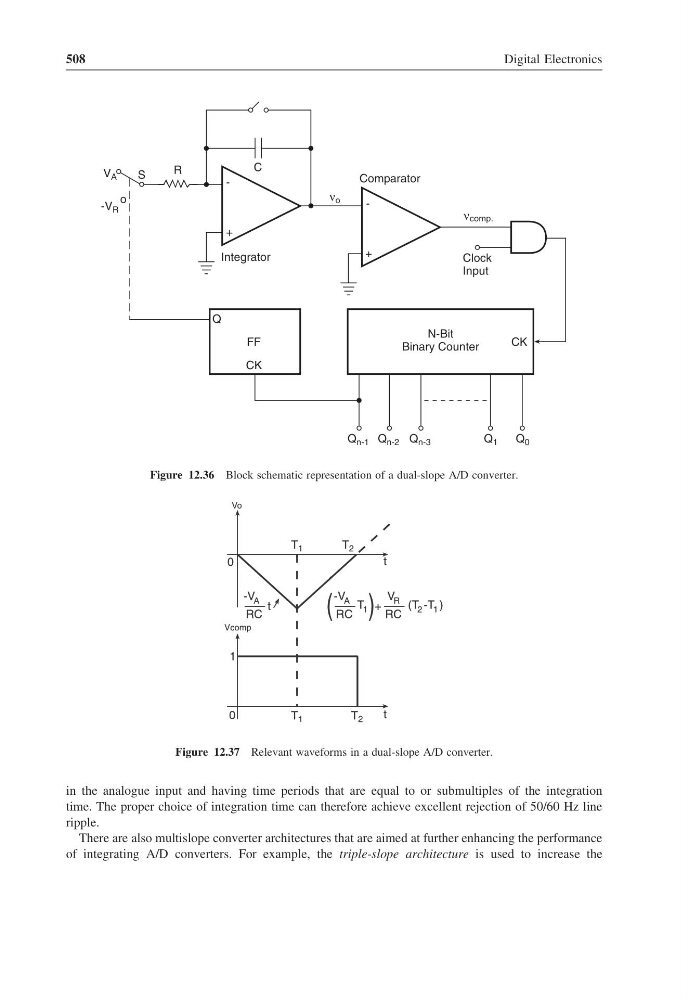
Figure 12.36 Block schematic representation of a dual-slope A/D converter.
T 1
-V A
RC
t
Vcomp
T 1
T 2
t
1
0
T 2
t
0
Vo
-V A
RC
T 1
V R
RC
(T -T )
2 1
( ) +
Figure 12.37 Relevant waveforms in a dual-slope A/D converter.
in the analogue input and having time periods that are equal to or submultiples of the integration
time. The proper choice of integration time can therefore achieve excellent rejection of 50/60 Hz line
ripple.
There are also multislope converter architectures that are aimed at further enhancing the performance
of integrating A/D converters. For example, the triple-slope architecture is used to increase the
Digital Electronics
-
+
R
V A
-
+
ν o
C
Integrator
Comparator
N-Bit
Binary Counter
Clock
Input
ν comp.
CK
CK
FF
Q
S
-V R
Q n-1 Q n-2 Q n-3
Q 1
Q 0
o
Figure 12.36 Block schematic representation of a dual-slope A/D converter.
T 1
-V A
RC
t
Vcomp
T 1
T 2
t
1
0
T 2
t
0
Vo
-V A
RC
T 1
V R
RC
(T -T )
2 1
( ) +
Figure 12.37 Relevant waveforms in a dual-slope A/D converter.
in the analogue input and having time periods that are equal to or submultiples of the integration
time. The proper choice of integration time can therefore achieve excellent rejection of 50/60 Hz line
ripple.
There are also multislope converter architectures that are aimed at further enhancing the performance
of integrating A/D converters. For example, the triple-slope architecture is used to increase the