

Data Conversion Circuits – D/A and A/D Converters
507
−
+
Comp.
Timing
&
Control
Binary
or
BCD Control
Clk IN
Reset
Latches
Ramp Generator
Digital Output
V A
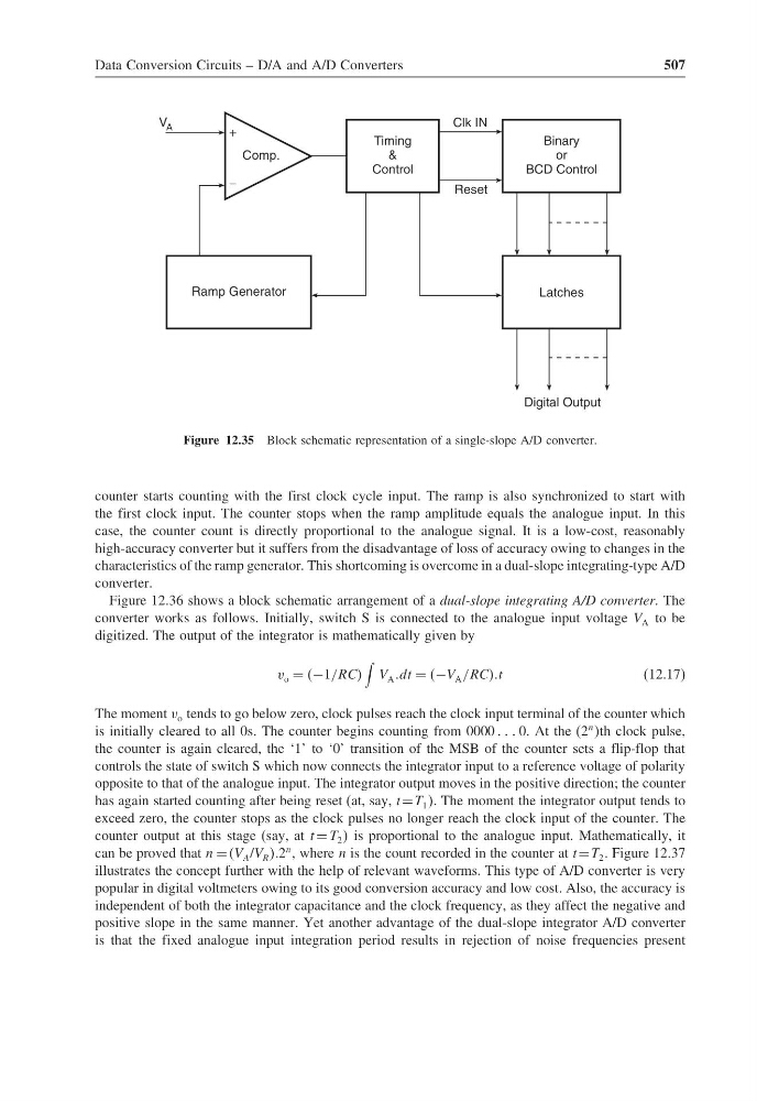
Figure 12.35 Block schematic representation of a single-slope A/D converter.
counter starts counting with the first clock cycle input. The ramp is also synchronized to start with
the first clock input. The counter stops when the ramp amplitude equals the analogue input. In this
case, the counter count is directly proportional to the analogue signal. It is a low-cost, reasonably
high-accuracy converter but it suffers from the disadvantage of loss of accuracy owing to changes in the
characteristics of the ramp generator. This shortcoming is overcome in a dual-slope integrating-type A/D
converter.
Figure 12.36 shows a block schematic arrangement of a dual-slope integrating A/D converter. The
converter works as follows. Initially, switch S is connected to the analogue input voltage V A to be
digitized. The output of the integrator is mathematically given by
v o = −1/RCC
V A dt = −V A /RCCCt
(12.17)
The moment v o tends to go below zero, clock pulses reach the clock input terminal of the counter which
is initially cleared to all 0s. The counter begins counting from 0000 0. At the (2
n th clock pulse,
the counter is again cleared, the ‘1’ to ‘0’ transition of the MSB of the counter sets a flip-flop that
controls the state of switch S which now connects the integrator input to a reference voltage of polarity
opposite to that of the analogue input. The integrator output moves in the positive direction; the counter
has again started counting after being reset (at, say, t =T 1 . The moment the integrator output tends to
exceed zero, the counter stops as the clock pulses no longer reach the clock input of the counter. The
counter output at this stage (say, at t = T 2 is proportional to the analogue input. Mathematically, it
can be proved that n = (V A /V R .2
n , where n is the count recorded in the counter at t=T 2 . Figure 12.37
illustrates the concept further with the help of relevant waveforms. This type of A/D converter is very
popular in digital voltmeters owing to its good conversion accuracy and low cost. Also, the accuracy is
independent of both the integrator capacitance and the clock frequency, as they affect the negative and
positive slope in the same manner. Yet another advantage of the dual-slope integrator A/D converter
is that the fixed analogue input integration period results in rejection of noise frequencies present
507
−
+
Comp.
Timing
&
Control
Binary
or
BCD Control
Clk IN
Reset
Latches
Ramp Generator
Digital Output
V A
Figure 12.35 Block schematic representation of a single-slope A/D converter.
counter starts counting with the first clock cycle input. The ramp is also synchronized to start with
the first clock input. The counter stops when the ramp amplitude equals the analogue input. In this
case, the counter count is directly proportional to the analogue signal. It is a low-cost, reasonably
high-accuracy converter but it suffers from the disadvantage of loss of accuracy owing to changes in the
characteristics of the ramp generator. This shortcoming is overcome in a dual-slope integrating-type A/D
converter.
Figure 12.36 shows a block schematic arrangement of a dual-slope integrating A/D converter. The
converter works as follows. Initially, switch S is connected to the analogue input voltage V A to be
digitized. The output of the integrator is mathematically given by
v o = −1/RCC
V A dt = −V A /RCCCt
(12.17)
The moment v o tends to go below zero, clock pulses reach the clock input terminal of the counter which
is initially cleared to all 0s. The counter begins counting from 0000 0. At the (2
n th clock pulse,
the counter is again cleared, the ‘1’ to ‘0’ transition of the MSB of the counter sets a flip-flop that
controls the state of switch S which now connects the integrator input to a reference voltage of polarity
opposite to that of the analogue input. The integrator output moves in the positive direction; the counter
has again started counting after being reset (at, say, t =T 1 . The moment the integrator output tends to
exceed zero, the counter stops as the clock pulses no longer reach the clock input of the counter. The
counter output at this stage (say, at t = T 2 is proportional to the analogue input. Mathematically, it
can be proved that n = (V A /V R .2
n , where n is the count recorded in the counter at t=T 2 . Figure 12.37
illustrates the concept further with the help of relevant waveforms. This type of A/D converter is very
popular in digital voltmeters owing to its good conversion accuracy and low cost. Also, the accuracy is
independent of both the integrator capacitance and the clock frequency, as they affect the negative and
positive slope in the same manner. Yet another advantage of the dual-slope integrator A/D converter
is that the fixed analogue input integration period results in rejection of noise frequencies present