

506
Digital Electronics
1111
1110
1101
1100
1011
1010
1001
1000
0111
0110
0101
0100
0011
0010
0001
0000
1111
1101
1011
1001
0111
0101
0011
0001
1110
1010
0110
0010
1100
0100
0000
1000
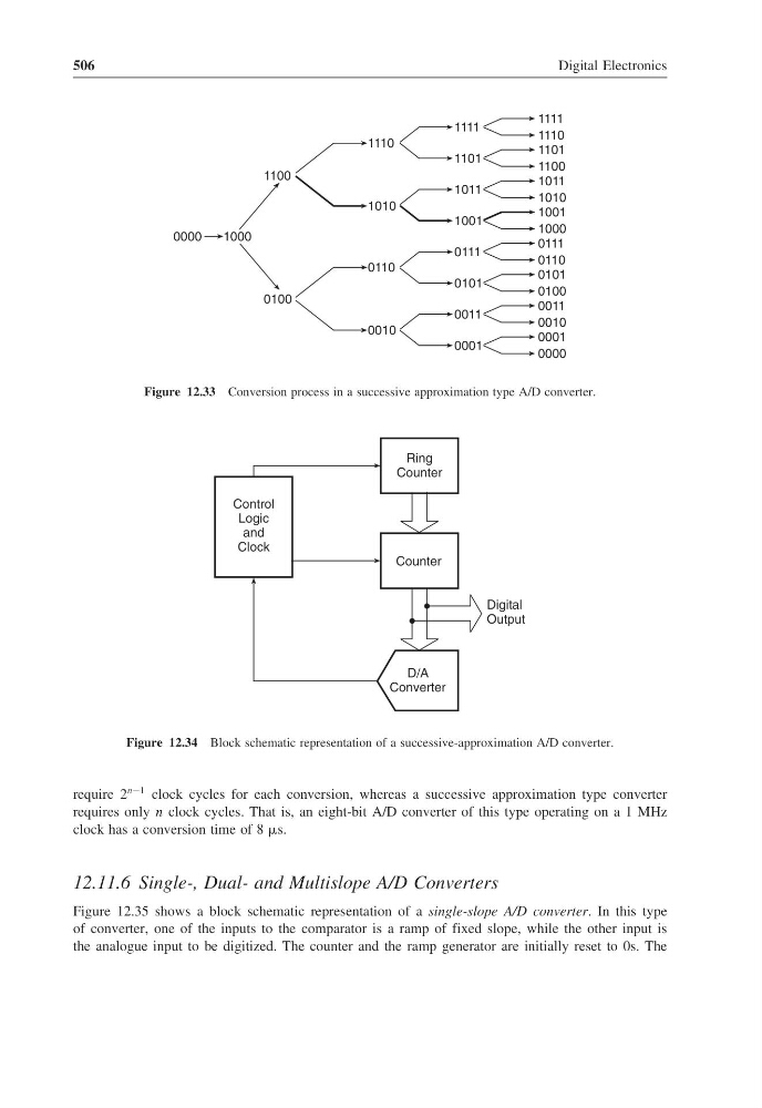
Figure 12.33 Conversion process in a successive approximation type A/D converter.
Counter
D/A
Converter
Digital
Output
Ring
Counter
Control
Logic
and
Clock
Figure 12.34 Block schematic representation of a successive-approximation A/D converter.
require 2
n−1 clock cycles for each conversion, whereas a successive approximation type converter
requires only n clock cycles. That is, an eight-bit A/D converter of this type operating on a 1 MHz
clock has a conversion time of 8 s.
12.11.6 Single-, Dual- and Multislope A/D Converters
Figure 12.35 shows a block schematic representation of a single-slope A/D converter. In this type
of converter, one of the inputs to the comparator is a ramp of fixed slope, while the other input is
the analogue input to be digitized. The counter and the ramp generator are initially reset to 0s. The
Digital Electronics
1111
1110
1101
1100
1011
1010
1001
1000
0111
0110
0101
0100
0011
0010
0001
0000
1111
1101
1011
1001
0111
0101
0011
0001
1110
1010
0110
0010
1100
0100
0000
1000
Figure 12.33 Conversion process in a successive approximation type A/D converter.
Counter
D/A
Converter
Digital
Output
Ring
Counter
Control
Logic
and
Clock
Figure 12.34 Block schematic representation of a successive-approximation A/D converter.
require 2
n−1 clock cycles for each conversion, whereas a successive approximation type converter
requires only n clock cycles. That is, an eight-bit A/D converter of this type operating on a 1 MHz
clock has a conversion time of 8 s.
12.11.6 Single-, Dual- and Multislope A/D Converters
Figure 12.35 shows a block schematic representation of a single-slope A/D converter. In this type
of converter, one of the inputs to the comparator is a ramp of fixed slope, while the other input is
the analogue input to be digitized. The counter and the ramp generator are initially reset to 0s. The