

504
Digital Electronics
into digital code using a least significant four-bit A/D converter. The least significant A/D converter
is referenced to one-sixteenth (= 1/2
4 of the reference voltage used by the most significant A/D
converter. The new four-bit digital output is stored in the least significant four bits of the output latch.
The latch now contains the eight-bit digital equivalent of the analogue input. The digitized output is
the same as would be produced by an eight-bit full-flash converter. The only difference is that the
conversion process takes a little longer. It may also be mentioned here that the eight-bit half-flash
converter can be used either as a four-bit full-flash converter or as an eight-bit half-flash converter.
Some half-flash converters use a single full-flash converter and reuse it for both conversions. This is
achieved by using additional sample-and-hold circuitry.
12.11.3 Counter-Type A/D Converter
It is possible to construct higher-resolution A/D converters with a single comparator by using a variable
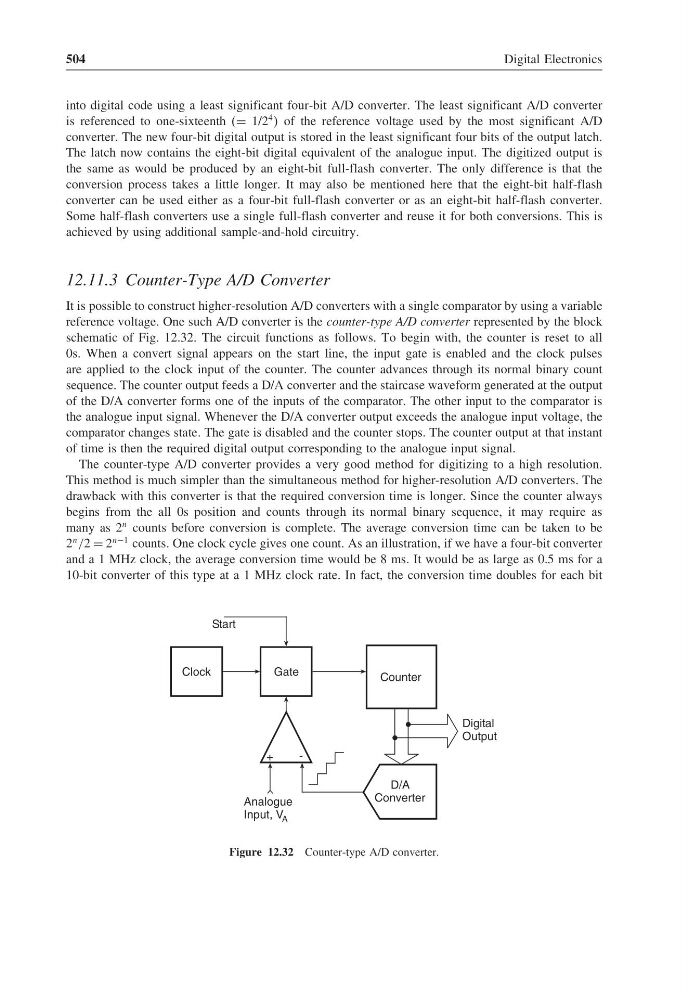
reference voltage. One such A/D converter is the counter-type A/D converter represented by the block
schematic of Fig. 12.32. The circuit functions as follows. To begin with, the counter is reset to all
0s. When a convert signal appears on the start line, the input gate is enabled and the clock pulses
are applied to the clock input of the counter. The counter advances through its normal binary count
sequence. The counter output feeds a D/A converter and the staircase waveform generated at the output
of the D/A converter forms one of the inputs of the comparator. The other input to the comparator is
the analogue input signal. Whenever the D/A converter output exceeds the analogue input voltage, the
comparator changes state. The gate is disabled and the counter stops. The counter output at that instant
of time is then the required digital output corresponding to the analogue input signal.
The counter-type A/D converter provides a very good method for digitizing to a high resolution.
This method is much simpler than the simultaneous method for higher-resolution A/D converters. The
drawback with this converter is that the required conversion time is longer. Since the counter always
begins from the all 0s position and counts through its normal binary sequence, it may require as
many as 2
n counts before conversion is complete. The average conversion time can be taken to be
2
n /2 = 2
n−1 counts. One clock cycle gives one count. As an illustration, if we have a four-bit converter
and a 1 MHz clock, the average conversion time would be 8 ms. It would be as large as 0.5 ms for a
10-bit converter of this type at a 1 MHz clock rate. In fact, the conversion time doubles for each bit
Gate
Clock
Counter
D/A
Converter
+
-
Analogue
Input, V A
Digital
Output
Start
Figure 12.32 Counter-type A/D converter.
Digital Electronics
into digital code using a least significant four-bit A/D converter. The least significant A/D converter
is referenced to one-sixteenth (= 1/2
4 of the reference voltage used by the most significant A/D
converter. The new four-bit digital output is stored in the least significant four bits of the output latch.
The latch now contains the eight-bit digital equivalent of the analogue input. The digitized output is
the same as would be produced by an eight-bit full-flash converter. The only difference is that the
conversion process takes a little longer. It may also be mentioned here that the eight-bit half-flash
converter can be used either as a four-bit full-flash converter or as an eight-bit half-flash converter.
Some half-flash converters use a single full-flash converter and reuse it for both conversions. This is
achieved by using additional sample-and-hold circuitry.
12.11.3 Counter-Type A/D Converter
It is possible to construct higher-resolution A/D converters with a single comparator by using a variable
reference voltage. One such A/D converter is the counter-type A/D converter represented by the block
schematic of Fig. 12.32. The circuit functions as follows. To begin with, the counter is reset to all
0s. When a convert signal appears on the start line, the input gate is enabled and the clock pulses
are applied to the clock input of the counter. The counter advances through its normal binary count
sequence. The counter output feeds a D/A converter and the staircase waveform generated at the output
of the D/A converter forms one of the inputs of the comparator. The other input to the comparator is
the analogue input signal. Whenever the D/A converter output exceeds the analogue input voltage, the
comparator changes state. The gate is disabled and the counter stops. The counter output at that instant
of time is then the required digital output corresponding to the analogue input signal.
The counter-type A/D converter provides a very good method for digitizing to a high resolution.
This method is much simpler than the simultaneous method for higher-resolution A/D converters. The
drawback with this converter is that the required conversion time is longer. Since the counter always
begins from the all 0s position and counts through its normal binary sequence, it may require as
many as 2
n counts before conversion is complete. The average conversion time can be taken to be
2
n /2 = 2
n−1 counts. One clock cycle gives one count. As an illustration, if we have a four-bit converter
and a 1 MHz clock, the average conversion time would be 8 ms. It would be as large as 0.5 ms for a
10-bit converter of this type at a 1 MHz clock rate. In fact, the conversion time doubles for each bit
Gate
Clock
Counter
D/A
Converter
+
-
Analogue
Input, V A
Digital
Output
Start
Figure 12.32 Counter-type A/D converter.