

Data Conversion Circuits – D/A and A/D Converters
503
comparators required to perform A/D conversion increases very rapidly, and it may not be feasible to
use this approach once the number of bits exceeds six or so. The greatest advantage of this technique
lies in its capability to execute extremely fast analogue-to-digital conversion.
12.11.2 Half-Flash A/D Converter
The half-flash A/D converter, also known as the pipeline A/D converter, is a variant of the flash-type
converter that largely overcomes the primary disadvantage of the high-resolution full-flash converter,
namely the prohibitively large number of comparators required, without significantly degrading its
high-speed conversion performance. Compared with a full-flash converter of certain resolution, while
the number of comparators and associated resistors is drastically reduced in a half-flash converter, the
conversion time increases approximately by a factor of 2. For an n-bit flash converter the number of
comparators required is 2
n 2
n
− 1) for encoding of amplitude and one comparator for polarity], while
the same for an equivalent half-flash converter would be 2 × 2
n/2 . In the case of an eight-bit converter,
the number is 32 (for half-flash) against 256 (for full flash). How it is achieved is explained in the
following paragraphs considering the example of an eight-bit half-flash converter.
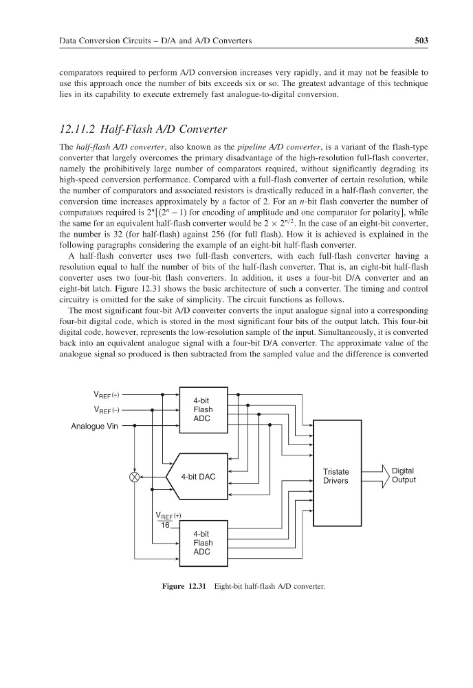
A half-flash converter uses two full-flash converters, with each full-flash converter having a
resolution equal to half the number of bits of the half-flash converter. That is, an eight-bit half-flash
converter uses two four-bit flash converters. In addition, it uses a four-bit D/A converter and an
eight-bit latch. Figure 12.31 shows the basic architecture of such a converter. The timing and control
circuitry is omitted for the sake of simplicity. The circuit functions as follows.
The most significant four-bit A/D converter converts the input analogue signal into a corresponding
four-bit digital code, which is stored in the most significant four bits of the output latch. This four-bit
digital code, however, represents the low-resolution sample of the input. Simultaneously, it is converted
back into an equivalent analogue signal with a four-bit D/A converter. The approximate value of the
analogue signal so produced is then subtracted from the sampled value and the difference is converted
4-bit
Flash
ADC
4-bit DAC
4-bit
Flash
ADC
V REF (+)
16
Tristate
Drivers
Digital
Output
V REF (+)
V REF ( )
−
Analogue Vin
Figure 12.31 Eight-bit half-flash A/D converter.
503
comparators required to perform A/D conversion increases very rapidly, and it may not be feasible to
use this approach once the number of bits exceeds six or so. The greatest advantage of this technique
lies in its capability to execute extremely fast analogue-to-digital conversion.
12.11.2 Half-Flash A/D Converter
The half-flash A/D converter, also known as the pipeline A/D converter, is a variant of the flash-type
converter that largely overcomes the primary disadvantage of the high-resolution full-flash converter,
namely the prohibitively large number of comparators required, without significantly degrading its
high-speed conversion performance. Compared with a full-flash converter of certain resolution, while
the number of comparators and associated resistors is drastically reduced in a half-flash converter, the
conversion time increases approximately by a factor of 2. For an n-bit flash converter the number of
comparators required is 2
n 2
n
− 1) for encoding of amplitude and one comparator for polarity], while
the same for an equivalent half-flash converter would be 2 × 2
n/2 . In the case of an eight-bit converter,
the number is 32 (for half-flash) against 256 (for full flash). How it is achieved is explained in the
following paragraphs considering the example of an eight-bit half-flash converter.
A half-flash converter uses two full-flash converters, with each full-flash converter having a
resolution equal to half the number of bits of the half-flash converter. That is, an eight-bit half-flash
converter uses two four-bit flash converters. In addition, it uses a four-bit D/A converter and an
eight-bit latch. Figure 12.31 shows the basic architecture of such a converter. The timing and control
circuitry is omitted for the sake of simplicity. The circuit functions as follows.
The most significant four-bit A/D converter converts the input analogue signal into a corresponding
four-bit digital code, which is stored in the most significant four bits of the output latch. This four-bit
digital code, however, represents the low-resolution sample of the input. Simultaneously, it is converted
back into an equivalent analogue signal with a four-bit D/A converter. The approximate value of the
analogue signal so produced is then subtracted from the sampled value and the difference is converted
4-bit
Flash
ADC
4-bit DAC
4-bit
Flash
ADC
V REF (+)
16
Tristate
Drivers
Digital
Output
V REF (+)
V REF ( )
−
Analogue Vin
Figure 12.31 Eight-bit half-flash A/D converter.