

Data Conversion Circuits – D/A and A/D Converters
481
2R
(Analog Ground)
R
R
R
2R
2R
2R
2R I/16
I/2
I/4
I/8
I/16
I
V ref
MSB
LSB
Out-1
R F = R
Out-2
(Digital Ground)
−
+
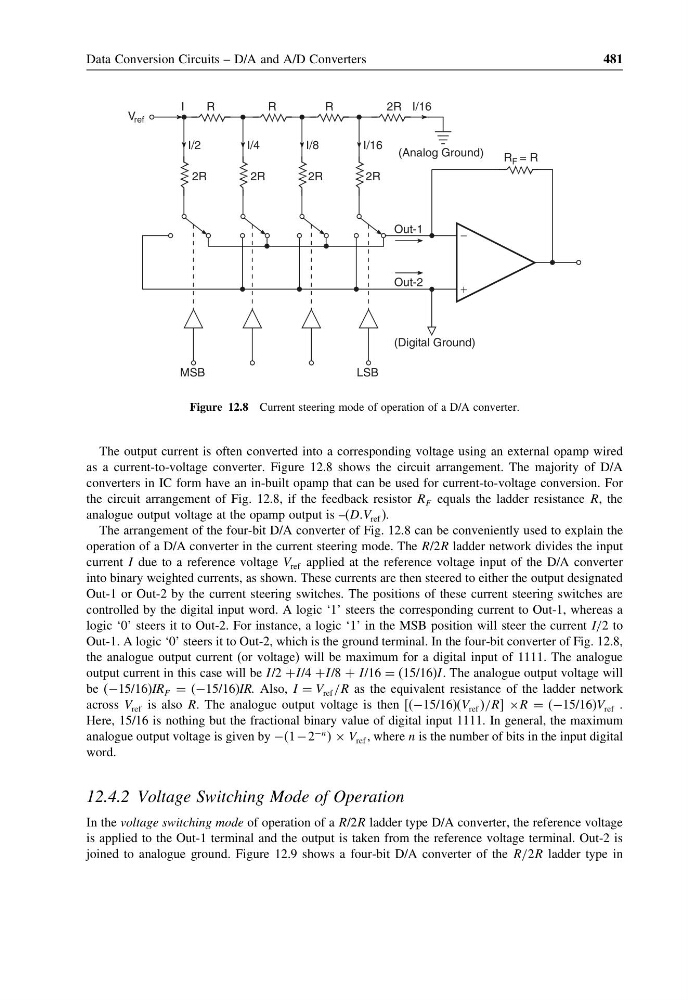
Figure 12.8 Current steering mode of operation of a D/A converter.
The output current is often converted into a corresponding voltage using an external opamp wired
as a current-to-voltage converter. Figure 12.8 shows the circuit arrangement. The majority of D/A
converters in IC form have an in-built opamp that can be used for current-to-voltage conversion. For
the circuit arrangement of Fig. 12.8, if the feedback resistor R F equals the ladder resistance R, the
analogue output voltage at the opamp output is –(DDV ref ).
The arrangement of the four-bit D/A converter of Fig. 12.8 can be conveniently used to explain the
operation of a D/A converter in the current steering mode. The R/2R ladder network divides the input
current I due to a reference voltage V ref applied at the reference voltage input of the D/A converter
into binary weighted currents, as shown. These currents are then steered to either the output designated
Out-1 or Out-2 by the current steering switches. The positions of these current steering switches are
controlled by the digital input word. A logic ‘1’ steers the corresponding current to Out-1, whereas a
logic ‘0’ steers it to Out-2. For instance, a logic ‘1’ in the MSB position will steer the current I/2 to
Out-1. A logic ‘0’ steers it to Out-2, which is the ground terminal. In the four-bit converter of Fig. 12.8,
the analogue output current (or voltage) will be maximum for a digital input of 1111. The analogue
output current in this case will be I/2 +I/4 +I/8 + I/16 = (15/16)I. The analogue output voltage will
be (−15/16)IR F = (−15/16)IR. Also, I = V ref /R as the equivalent resistance of the ladder network
across V ref is also RR The analogue output voltage is then [(−15/16)(V ref /R] ×R = (−15/16)V ref
Here, 15/16 is nothing but the fractional binary value of digital input 1111. In general, the maximum
analogue output voltage is given by −1 − 2
−n × V ref , where n is the number of bits in the input digital
word.
12.4.2 Voltage Switching Mode of Operation
In the voltage switching mode of operation of a R/2R ladder type D/A converter, the reference voltage
is applied to the Out-1 terminal and the output is taken from the reference voltage terminal. Out-2 is
joined to analogue ground. Figure 12.9 shows a four-bit D/A converter of the R/2R ladder type in
481
2R
(Analog Ground)
R
R
R
2R
2R
2R
2R I/16
I/2
I/4
I/8
I/16
I
V ref
MSB
LSB
Out-1
R F = R
Out-2
(Digital Ground)
−
+
Figure 12.8 Current steering mode of operation of a D/A converter.
The output current is often converted into a corresponding voltage using an external opamp wired
as a current-to-voltage converter. Figure 12.8 shows the circuit arrangement. The majority of D/A
converters in IC form have an in-built opamp that can be used for current-to-voltage conversion. For
the circuit arrangement of Fig. 12.8, if the feedback resistor R F equals the ladder resistance R, the
analogue output voltage at the opamp output is –(DDV ref ).
The arrangement of the four-bit D/A converter of Fig. 12.8 can be conveniently used to explain the
operation of a D/A converter in the current steering mode. The R/2R ladder network divides the input
current I due to a reference voltage V ref applied at the reference voltage input of the D/A converter
into binary weighted currents, as shown. These currents are then steered to either the output designated
Out-1 or Out-2 by the current steering switches. The positions of these current steering switches are
controlled by the digital input word. A logic ‘1’ steers the corresponding current to Out-1, whereas a
logic ‘0’ steers it to Out-2. For instance, a logic ‘1’ in the MSB position will steer the current I/2 to
Out-1. A logic ‘0’ steers it to Out-2, which is the ground terminal. In the four-bit converter of Fig. 12.8,
the analogue output current (or voltage) will be maximum for a digital input of 1111. The analogue
output current in this case will be I/2 +I/4 +I/8 + I/16 = (15/16)I. The analogue output voltage will
be (−15/16)IR F = (−15/16)IR. Also, I = V ref /R as the equivalent resistance of the ladder network
across V ref is also RR The analogue output voltage is then [(−15/16)(V ref /R] ×R = (−15/16)V ref
Here, 15/16 is nothing but the fractional binary value of digital input 1111. In general, the maximum
analogue output voltage is given by −1 − 2
−n × V ref , where n is the number of bits in the input digital
word.
12.4.2 Voltage Switching Mode of Operation
In the voltage switching mode of operation of a R/2R ladder type D/A converter, the reference voltage
is applied to the Out-1 terminal and the output is taken from the reference voltage terminal. Out-2 is
joined to analogue ground. Figure 12.9 shows a four-bit D/A converter of the R/2R ladder type in