

482
Digital Electronics
2R
R
R
R
2R
2R
2R
2R
V ref
MSB
LSB
Out-1
Out-2
(Angle O/P)
-
+
(Digital Ground)
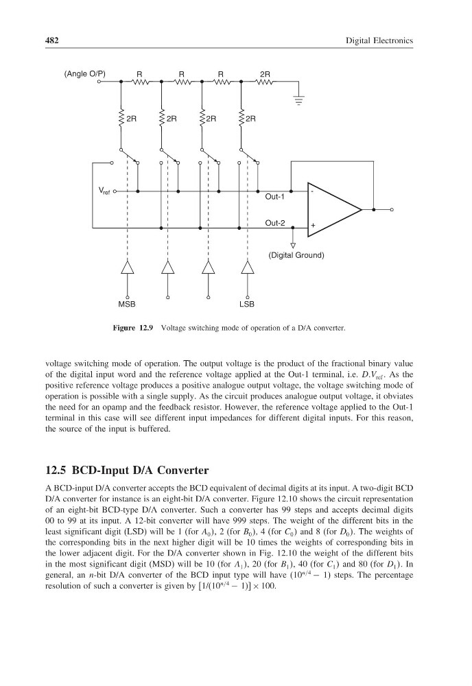
Figure 12.9 Voltage switching mode of operation of a D/A converter.
voltage switching mode of operation. The output voltage is the product of the fractional binary value
of the digital input word and the reference voltage applied at the Out-1 terminal, i.e. DDV ref As the
positive reference voltage produces a positive analogue output voltage, the voltage switching mode of
operation is possible with a single supply. As the circuit produces analogue output voltage, it obviates
the need for an opamp and the feedback resistor. However, the reference voltage applied to the Out-1
terminal in this case will see different input impedances for different digital inputs. For this reason,
the source of the input is buffered.
12.5 BCD-Input D/A Converter
A BCD-input D/A converter accepts the BCD equivalent of decimal digits at its input. A two-digit BCD
D/A converter for instance is an eight-bit D/A converter. Figure 12.10 shows the circuit representation
of an eight-bit BCD-type D/A converter. Such a converter has 99 steps and accepts decimal digits
00 to 99 at its input. A 12-bit converter will have 999 steps. The weight of the different bits in the
least significant digit (LSD) will be 1 (for A 0 , 2 (for B 0 , 4 (for C 0 and 8 (for D 0 The weights of
the corresponding bits in the next higher digit will be 10 times the weights of corresponding bits in
the lower adjacent digit. For the D/A converter shown in Fig. 12.10 the weight of the different bits
in the most significant digit (MSD) will be 10 (for A 1 , 20 (for B 1 , 40 (for C 1 and 80 (for D 1 In
general, an n-bit D/A converter of the BCD input type will have (10
n/4
− 1) steps. The percentage
resolution of such a converter is given by [1/(10
n/4
− 1)] × 100.
Digital Electronics
2R
R
R
R
2R
2R
2R
2R
V ref
MSB
LSB
Out-1
Out-2
(Angle O/P)
-
+
(Digital Ground)
Figure 12.9 Voltage switching mode of operation of a D/A converter.
voltage switching mode of operation. The output voltage is the product of the fractional binary value
of the digital input word and the reference voltage applied at the Out-1 terminal, i.e. DDV ref As the
positive reference voltage produces a positive analogue output voltage, the voltage switching mode of
operation is possible with a single supply. As the circuit produces analogue output voltage, it obviates
the need for an opamp and the feedback resistor. However, the reference voltage applied to the Out-1
terminal in this case will see different input impedances for different digital inputs. For this reason,
the source of the input is buffered.
12.5 BCD-Input D/A Converter
A BCD-input D/A converter accepts the BCD equivalent of decimal digits at its input. A two-digit BCD
D/A converter for instance is an eight-bit D/A converter. Figure 12.10 shows the circuit representation
of an eight-bit BCD-type D/A converter. Such a converter has 99 steps and accepts decimal digits
00 to 99 at its input. A 12-bit converter will have 999 steps. The weight of the different bits in the
least significant digit (LSD) will be 1 (for A 0 , 2 (for B 0 , 4 (for C 0 and 8 (for D 0 The weights of
the corresponding bits in the next higher digit will be 10 times the weights of corresponding bits in
the lower adjacent digit. For the D/A converter shown in Fig. 12.10 the weight of the different bits
in the most significant digit (MSD) will be 10 (for A 1 , 20 (for B 1 , 40 (for C 1 and 80 (for D 1 In
general, an n-bit D/A converter of the BCD input type will have (10
n/4
− 1) steps. The percentage
resolution of such a converter is given by [1/(10
n/4
− 1)] × 100.