

Data Conversion Circuits – D/A and A/D Converters
477
have a percentage resolution of (1/255) × 100 = 0.39 % or simply an eight-bit resolution. A 12-bit D/A
converter would have a percentage resolution of (1/4095) × 100 = 0.0244 %. In general, for an n-bit
D/A converter, the percentage resolution is given by (1/2
n
− 1) × 100. The resolution in millivolts for
the two cases for a full-scale output of 5 V is approximately 20 mV (for an eight-bit converter) and
1.2 mV (for a 12-bit converter).
12.2.2 Accuracy
The accuracy of a D/A converter is the difference between the actual analogue output and the ideal
expected output when a given digital input is applied. Sources of error include the gain error (or
full-scale error), the offset error (or zero-scale error), nonlinearity errors and a drift of all these factors.
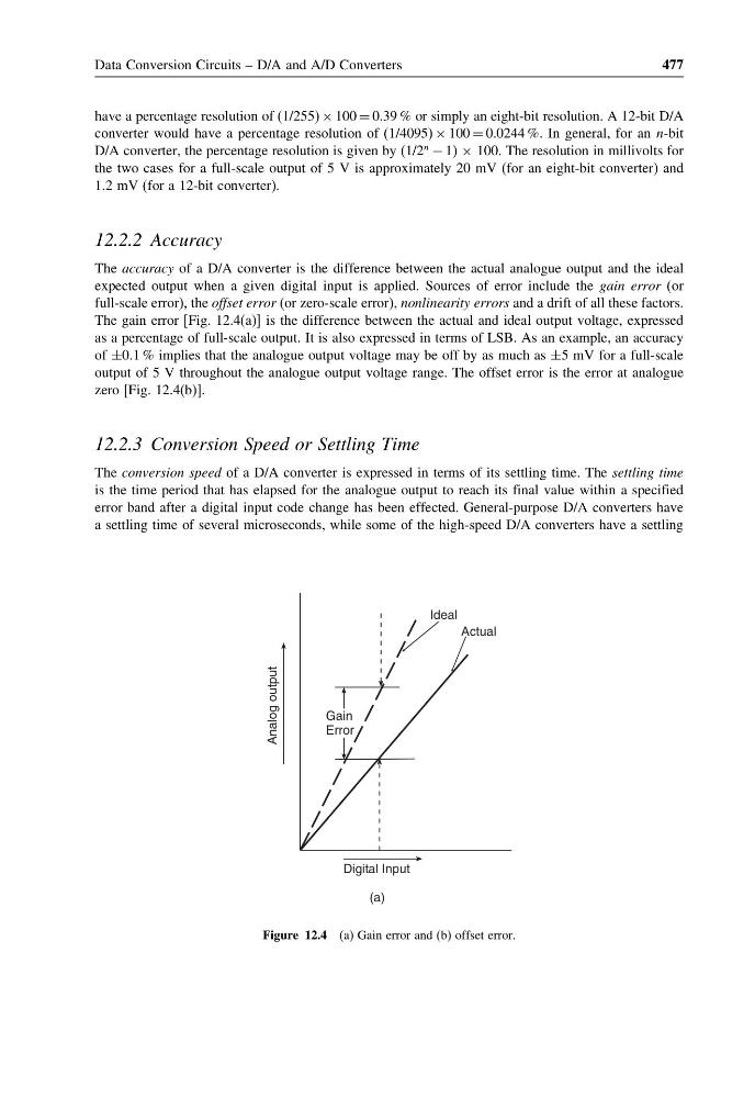
The gain error [Fig. 12.4(a)] is the difference between the actual and ideal output voltage, expressed
as a percentage of full-scale output. It is also expressed in terms of LSB. As an example, an accuracy
of ±0.1 % implies that the analogue output voltage may be off by as much as ±5 mV for a full-scale
output of 5 V throughout the analogue output voltage range. The offset error is the error at analogue
zero [Fig. 12.4(b)].
12.2.3 Conversion Speed or Settling Time
The conversion speed of a D/A converter is expressed in terms of its settling time. The settling time
is the time period that has elapsed for the analogue output to reach its final value within a specified
error band after a digital input code change has been effected. General-purpose D/A converters have
a settling time of several microseconds, while some of the high-speed D/A converters have a settling
Ideal
Actual
Analog output
Digital Input
Gain
Error
(a)
Figure 12.4 (a) Gain error and (b) offset error.
477
have a percentage resolution of (1/255) × 100 = 0.39 % or simply an eight-bit resolution. A 12-bit D/A
converter would have a percentage resolution of (1/4095) × 100 = 0.0244 %. In general, for an n-bit
D/A converter, the percentage resolution is given by (1/2
n
− 1) × 100. The resolution in millivolts for
the two cases for a full-scale output of 5 V is approximately 20 mV (for an eight-bit converter) and
1.2 mV (for a 12-bit converter).
12.2.2 Accuracy
The accuracy of a D/A converter is the difference between the actual analogue output and the ideal
expected output when a given digital input is applied. Sources of error include the gain error (or
full-scale error), the offset error (or zero-scale error), nonlinearity errors and a drift of all these factors.
The gain error [Fig. 12.4(a)] is the difference between the actual and ideal output voltage, expressed
as a percentage of full-scale output. It is also expressed in terms of LSB. As an example, an accuracy
of ±0.1 % implies that the analogue output voltage may be off by as much as ±5 mV for a full-scale
output of 5 V throughout the analogue output voltage range. The offset error is the error at analogue
zero [Fig. 12.4(b)].
12.2.3 Conversion Speed or Settling Time
The conversion speed of a D/A converter is expressed in terms of its settling time. The settling time
is the time period that has elapsed for the analogue output to reach its final value within a specified
error band after a digital input code change has been effected. General-purpose D/A converters have
a settling time of several microseconds, while some of the high-speed D/A converters have a settling
Ideal
Actual
Analog output
Digital Input
Gain
Error
(a)
Figure 12.4 (a) Gain error and (b) offset error.