

476
Digital Electronics
V A
Input
Gates
n-bit
Digital Input
n-bit
Register
n-Lines
Level
Amplifiers
Binary
Ladder
n-Lines
n-Lines
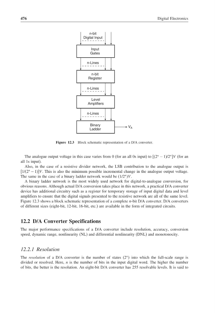
Figure 12.3 Block schematic representation of a D/A converter.
The analogue output voltage in this case varies from 0 (for an all 0s input) to [(2
n
− 1)/2
n ]V (for an
all 1s input).
Also, in the case of a resistive divider network, the LSB contribution to the analogue output is
[1/(2
n
− 1)]V . This is also the minimum possible incremental change in the analogue output voltage.
The same in the case of a binary ladder network would be (1/2
n V .
A binary ladder network is the most widely used network for digital-to-analogue conversion, for
obvious reasons. Although actual D/A conversion takes place in this network, a practical D/A converter
device has additional circuitry such as a register for temporary storage of input digital data and level
amplifiers to ensure that the digital signals presented to the resistive network are all of the same level.
Figure 12.3 shows a block schematic representation of a complete n-bit D/A converter. D/A converters
of different sizes (eight-bit, 12-bit, 16-bit, etc.) are available in the form of integrated circuits.
12.2 D/A Converter Specifications
The major performance specifications of a D/A converter include resolution, accuracy, conversion
speed, dynamic range, nonlinearity (NL) and differential nonlinearity (DNL) and monotonocity.
12.2.1 Resolution
The resolution of a D/A converter is the number of states (2
n into which the full-scale range is
divided or resolved. Here, n is the number of bits in the input digital word. The higher the number
of bits, the better is the resolution. An eight-bit D/A converter has 255 resolvable levels. It is said to
Digital Electronics
V A
Input
Gates
n-bit
Digital Input
n-bit
Register
n-Lines
Level
Amplifiers
Binary
Ladder
n-Lines
n-Lines
Figure 12.3 Block schematic representation of a D/A converter.
The analogue output voltage in this case varies from 0 (for an all 0s input) to [(2
n
− 1)/2
n ]V (for an
all 1s input).
Also, in the case of a resistive divider network, the LSB contribution to the analogue output is
[1/(2
n
− 1)]V . This is also the minimum possible incremental change in the analogue output voltage.
The same in the case of a binary ladder network would be (1/2
n V .
A binary ladder network is the most widely used network for digital-to-analogue conversion, for
obvious reasons. Although actual D/A conversion takes place in this network, a practical D/A converter
device has additional circuitry such as a register for temporary storage of input digital data and level
amplifiers to ensure that the digital signals presented to the resistive network are all of the same level.
Figure 12.3 shows a block schematic representation of a complete n-bit D/A converter. D/A converters
of different sizes (eight-bit, 12-bit, 16-bit, etc.) are available in the form of integrated circuits.
12.2 D/A Converter Specifications
The major performance specifications of a D/A converter include resolution, accuracy, conversion
speed, dynamic range, nonlinearity (NL) and differential nonlinearity (DNL) and monotonocity.
12.2.1 Resolution
The resolution of a D/A converter is the number of states (2
n into which the full-scale range is
divided or resolved. Here, n is the number of bits in the input digital word. The higher the number
of bits, the better is the resolution. An eight-bit D/A converter has 255 resolvable levels. It is said to