

470
Digital Electronics
4. Three four-bit BCD decade counters are connected in cascade. The MSB output of the first counter
is fed to the clock input of the second counter, and the MSB output of the second counter is fed
to the clock input of the third counter. If the counters are negatively edge triggered and the input
clock frequency is 256 kHz, what is the frequency of the waveform available at the MSB of the
third counter?
256 Hz
5. The flip-flops used in a four-bit binary ripple counter have a HIGH-to-LOW and LOW-to-HIGH
propagation delay of 25 and 10 ns respectively. Determine the maximum usable clock frequency
of this counter.
10 MHz
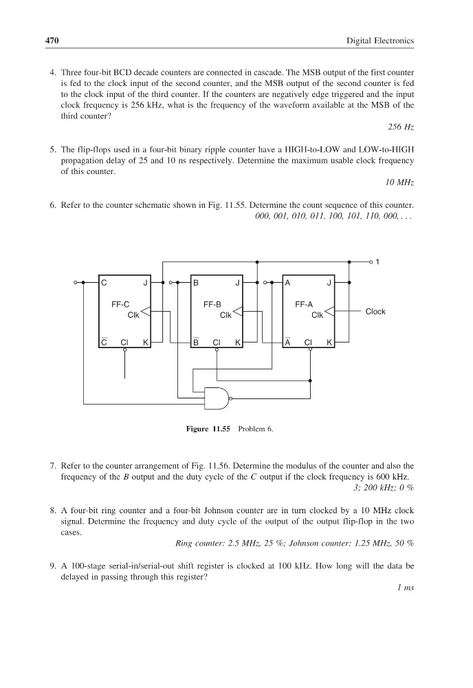
6. Refer to the counter schematic shown in Fig. 11.55. Determine the count sequence of this counter.
000, 001, 010, 011, 100, 101, 110, 000,
FF-C
C
C
J
K
Cl
Clk
FF-B
B
B
J
K
Cl
Clk
FF-A
A
A
J
K
Cl
Clk
Clock
1
Figure 11.55 Problem 6.
7. Refer to the counter arrangement of Fig. 11.56. Determine the modulus of the counter and also the
frequency of the B output and the duty cycle of the C output if the clock frequency is 600 kHz.
3; 200 kHz; 0 %
8. A four-bit ring counter and a four-bit Johnson counter are in turn clocked by a 10 MHz clock
signal. Determine the frequency and duty cycle of the output of the output flip-flop in the two
cases.
Ring counter: 2.5 MHz, 25 %; Johnson counter: 1.25 MHz, 50 %
9. A 100-stage serial-in/serial-out shift register is clocked at 100 kHz. How long will the data be
delayed in passing through this register?
1 ms
Digital Electronics
4. Three four-bit BCD decade counters are connected in cascade. The MSB output of the first counter
is fed to the clock input of the second counter, and the MSB output of the second counter is fed
to the clock input of the third counter. If the counters are negatively edge triggered and the input
clock frequency is 256 kHz, what is the frequency of the waveform available at the MSB of the
third counter?
256 Hz
5. The flip-flops used in a four-bit binary ripple counter have a HIGH-to-LOW and LOW-to-HIGH
propagation delay of 25 and 10 ns respectively. Determine the maximum usable clock frequency
of this counter.
10 MHz
6. Refer to the counter schematic shown in Fig. 11.55. Determine the count sequence of this counter.
000, 001, 010, 011, 100, 101, 110, 000,
FF-C
C
C
J
K
Cl
Clk
FF-B
B
B
J
K
Cl
Clk
FF-A
A
A
J
K
Cl
Clk
Clock
1
Figure 11.55 Problem 6.
7. Refer to the counter arrangement of Fig. 11.56. Determine the modulus of the counter and also the
frequency of the B output and the duty cycle of the C output if the clock frequency is 600 kHz.
3; 200 kHz; 0 %
8. A four-bit ring counter and a four-bit Johnson counter are in turn clocked by a 10 MHz clock
signal. Determine the frequency and duty cycle of the output of the output flip-flop in the two
cases.
Ring counter: 2.5 MHz, 25 %; Johnson counter: 1.25 MHz, 50 %
9. A 100-stage serial-in/serial-out shift register is clocked at 100 kHz. How long will the data be
delayed in passing through this register?
1 ms