

Counters and Registers
465
DIV2
(14)
CKA
DIV5
3CT=1
3CT=4
CT
0
2
(9)
(8)
(11)
(12) QA
QB
QC
QD
+
(2)
(3)
(6)
(7)
R0(1)
R0(2)
R9(1)
R9(2)
&
&
CTR
CT=0
Z3
(14)
(5)
(4)
(11)
(15)
(1)
(10)
(9)
(3)
(2)
(6)
(7)
[1]
[2]
[4]
[8]
3D
QA
QB
QC
QD
(12)
(13)
CTRDIV 16
1CT = 15
2CT = 0
CO
BO
LOAD
DOWN
UP
CLR
(a)
(b)
(1)
CKB
+
D
C
B
A
2+
G1
1−
G2
C3
CT=0
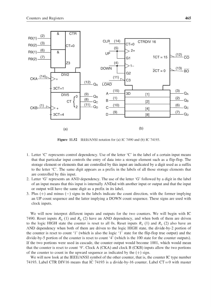
Figure 11.52 IEEE/ANSI notation for (a) IC 7490 and (b) IC 74193.
1. Letter ‘C’ represents control dependency. Use of the letter ‘C’ in the label of a certain input means
that that particular input controls the entry of data into a storage element such as a flip-flop. The
storage element or elements that are controlled by this input are indicated by a digit used as a suffix
to the letter ‘C’. The same digit appears as a prefix in the labels of all those storage elements that
are controlled by this input.
2. Letter ‘G’ represents an AND dependency. The use of the letter ‘G’ followed by a digit in the label
of an input means that this input is internally ANDed with another input or output and that the input
or output will have the same digit as a prefix in its label.
3. Plus (+) and minus (−) signs in the labels indicate the count direction, with the former implying
an UP count sequence and the latter implying a DOWN count sequence. These signs are used with
clock inputs.
We will now interpret different inputs and outputs for the two counters. We will begin with IC
7490. Reset inputs R 0 (1) and R 0 (2) have an AND dependency, and when both of them are driven
to the logic HIGH state the counter is reset to all 0s. Reset inputs R 9 (1) and R 9 (2) also have an
AND dependency when both of them are driven to the logic HIGH state, the divide-by-2 portion of
the counter is reset to count ‘1’ (which is also the logic ‘1’ state for the flip-flop true output) and the
divide-by-5 portion of the counter is reset to count ‘4’ (which is the 100 state for the counter outputs).
If the two portions were used in cascade, the counter output would become 1001, which would mean
that the counter is reset to count ‘9’. Clock A (CKA) and clock B (CKB) inputs allow the two portions
of the counter to count in the upward sequence as indicated by the (+) sign.
We will now look at the IEEE/ANSI symbol of the other counter, that is, the counter IC type number
74193. Label CTR DIV16 means that IC 74193 is a divide-by-16 counter. Label CT = 0 with master
465
DIV2
(14)
CKA
DIV5
3CT=1
3CT=4
CT
0
2
(9)
(8)
(11)
(12) QA
QB
QC
QD
+
(2)
(3)
(6)
(7)
R0(1)
R0(2)
R9(1)
R9(2)
&
&
CTR
CT=0
Z3
(14)
(5)
(4)
(11)
(15)
(1)
(10)
(9)
(3)
(2)
(6)
(7)
[1]
[2]
[4]
[8]
3D
QA
QB
QC
QD
(12)
(13)
CTRDIV 16
1CT = 15
2CT = 0
CO
BO
LOAD
DOWN
UP
CLR
(a)
(b)
(1)
CKB
+
D
C
B
A
2+
G1
1−
G2
C3
CT=0
Figure 11.52 IEEE/ANSI notation for (a) IC 7490 and (b) IC 74193.
1. Letter ‘C’ represents control dependency. Use of the letter ‘C’ in the label of a certain input means
that that particular input controls the entry of data into a storage element such as a flip-flop. The
storage element or elements that are controlled by this input are indicated by a digit used as a suffix
to the letter ‘C’. The same digit appears as a prefix in the labels of all those storage elements that
are controlled by this input.
2. Letter ‘G’ represents an AND dependency. The use of the letter ‘G’ followed by a digit in the label
of an input means that this input is internally ANDed with another input or output and that the input
or output will have the same digit as a prefix in its label.
3. Plus (+) and minus (−) signs in the labels indicate the count direction, with the former implying
an UP count sequence and the latter implying a DOWN count sequence. These signs are used with
clock inputs.
We will now interpret different inputs and outputs for the two counters. We will begin with IC
7490. Reset inputs R 0 (1) and R 0 (2) have an AND dependency, and when both of them are driven
to the logic HIGH state the counter is reset to all 0s. Reset inputs R 9 (1) and R 9 (2) also have an
AND dependency when both of them are driven to the logic HIGH state, the divide-by-2 portion of
the counter is reset to count ‘1’ (which is also the logic ‘1’ state for the flip-flop true output) and the
divide-by-5 portion of the counter is reset to count ‘4’ (which is the 100 state for the counter outputs).
If the two portions were used in cascade, the counter output would become 1001, which would mean
that the counter is reset to count ‘9’. Clock A (CKA) and clock B (CKB) inputs allow the two portions
of the counter to count in the upward sequence as indicated by the (+) sign.
We will now look at the IEEE/ANSI symbol of the other counter, that is, the counter IC type number
74193. Label CTR DIV16 means that IC 74193 is a divide-by-16 counter. Label CT = 0 with master