

460
Digital Electronics
Clock
Q -Output
0
Q -Output
1
Q -Output
2
Q -Output
3
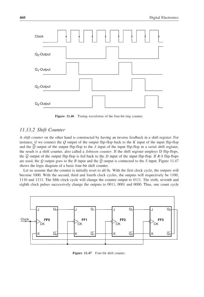
Figure 11.46 Timing waveforms of the four-bit ring counter.
11.13.2 Shift Counter
A shift counter on the other hand is constructed by having an inverse feedback in a shift register. For
instance, if we connect the Q output of the output flip-flop back to the K input of the input flip-flop
and the Q output of the output flip-flop to the J input of the input flip-flop in a serial shift register,
the result is a shift counter, also called a Johnson counter. If the shift register employs D flip-flops,
the Q output of the output flip-flop is fed back to the D input of the input flip-flop. If R-S flip-flops
are used, the Q output goes to the R input and the Q output is connected to the S input. Figure 11.47
shows the logic diagram of a basic four-bit shift counter.
Let us assume that the counter is initially reset to all 0s. With the first clock cycle, the outputs will
become 1000. With the second, third and fourth clock cycles, the outputs will respectively be 1100,
1110 and 1111. The fifth clock cycle will change the counter output to 0111. The sixth, seventh and
eighth clock pulses successively change the outputs to 0011, 0001 and 0000. Thus, one count cycle
Q 0
FF0
J
CK
Q 0
K
Q 1
FF1
J
CK
Q 1
K
Q 2
FF2
J
CK
Q 2
K
Q 3
FF3
J
CK
Q 3
K
Clock
Figure 11.47 Four-bit shift counter.
Digital Electronics
Clock
Q -Output
0
Q -Output
1
Q -Output
2
Q -Output
3
Figure 11.46 Timing waveforms of the four-bit ring counter.
11.13.2 Shift Counter
A shift counter on the other hand is constructed by having an inverse feedback in a shift register. For
instance, if we connect the Q output of the output flip-flop back to the K input of the input flip-flop
and the Q output of the output flip-flop to the J input of the input flip-flop in a serial shift register,
the result is a shift counter, also called a Johnson counter. If the shift register employs D flip-flops,
the Q output of the output flip-flop is fed back to the D input of the input flip-flop. If R-S flip-flops
are used, the Q output goes to the R input and the Q output is connected to the S input. Figure 11.47
shows the logic diagram of a basic four-bit shift counter.
Let us assume that the counter is initially reset to all 0s. With the first clock cycle, the outputs will
become 1000. With the second, third and fourth clock cycles, the outputs will respectively be 1100,
1110 and 1111. The fifth clock cycle will change the counter output to 0111. The sixth, seventh and
eighth clock pulses successively change the outputs to 0011, 0001 and 0000. Thus, one count cycle
Q 0
FF0
J
CK
Q 0
K
Q 1
FF1
J
CK
Q 1
K
Q 2
FF2
J
CK
Q 2
K
Q 3
FF3
J
CK
Q 3
K
Clock
Figure 11.47 Four-bit shift counter.