

Counters and Registers
459
11.13 Shift Register Counters
We have seen that both counters and shift registers are some kinds of cascade arrangement of
flip-flops. A shift register, unlike a counter, has no specified sequence of states. However, if the
serial output of the shift register is fed back to the serial input, we do get a circuit that exhibits a
specified sequence of states. The resulting circuits are known as shift register counters. Depending
upon the nature of the feedback, we have two types of shift register counter, namely the ring counter
and the shift counter, also called the Johnson counter. These are briefly described in the following
paragraphs.
11.13.1 Ring Counter
A ring counter is obtained from a shift register by directly feeding back the true output of the output
flip-flop to the data input terminal of the input flip-flop. If D flip-flops are being used to construct
the shift register, the ring counter, also called a circulating register, can be constructed by feeding
back the Q output of the output flip-flop back to the D input of the input flip-flop. If J-K flip-flops
are being used, the Q and Q outputs of the output flip-flop are respectively fed back to the J and K
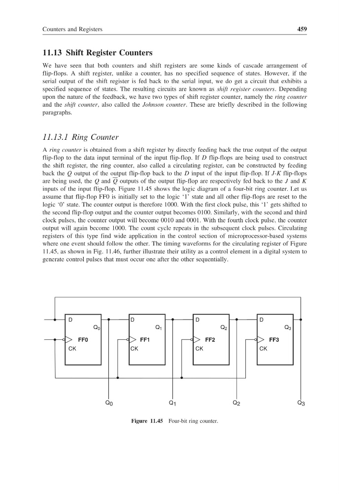
inputs of the input flip-flop. Figure 11.45 shows the logic diagram of a four-bit ring counter. Let us
assume that flip-flop FF0 is initially set to the logic ‘1’ state and all other flip-flops are reset to the
logic ‘0’ state. The counter output is therefore 1000. With the first clock pulse, this ‘1’ gets shifted to
the second flip-flop output and the counter output becomes 0100. Similarly, with the second and third
clock pulses, the counter output will become 0010 and 0001. With the fourth clock pulse, the counter
output will again become 1000. The count cycle repeats in the subsequent clock pulses. Circulating
registers of this type find wide application in the control section of microprocessor-based systems
where one event should follow the other. The timing waveforms for the circulating register of Figure
11.45, as shown in Fig. 11.46, further illustrate their utility as a control element in a digital system to
generate control pulses that must occur one after the other sequentially.
Q 0
FF0
D
CK
Q 1
FF1
D
CK
Q 2
FF2
D
CK
Q 3
FF3
D
CK
Q 0
Q 1
Q 2
Q 3
Figure 11.45 Four-bit ring counter.
459
11.13 Shift Register Counters
We have seen that both counters and shift registers are some kinds of cascade arrangement of
flip-flops. A shift register, unlike a counter, has no specified sequence of states. However, if the
serial output of the shift register is fed back to the serial input, we do get a circuit that exhibits a
specified sequence of states. The resulting circuits are known as shift register counters. Depending
upon the nature of the feedback, we have two types of shift register counter, namely the ring counter
and the shift counter, also called the Johnson counter. These are briefly described in the following
paragraphs.
11.13.1 Ring Counter
A ring counter is obtained from a shift register by directly feeding back the true output of the output
flip-flop to the data input terminal of the input flip-flop. If D flip-flops are being used to construct
the shift register, the ring counter, also called a circulating register, can be constructed by feeding
back the Q output of the output flip-flop back to the D input of the input flip-flop. If J-K flip-flops
are being used, the Q and Q outputs of the output flip-flop are respectively fed back to the J and K
inputs of the input flip-flop. Figure 11.45 shows the logic diagram of a four-bit ring counter. Let us
assume that flip-flop FF0 is initially set to the logic ‘1’ state and all other flip-flops are reset to the
logic ‘0’ state. The counter output is therefore 1000. With the first clock pulse, this ‘1’ gets shifted to
the second flip-flop output and the counter output becomes 0100. Similarly, with the second and third
clock pulses, the counter output will become 0010 and 0001. With the fourth clock pulse, the counter
output will again become 1000. The count cycle repeats in the subsequent clock pulses. Circulating
registers of this type find wide application in the control section of microprocessor-based systems
where one event should follow the other. The timing waveforms for the circulating register of Figure
11.45, as shown in Fig. 11.46, further illustrate their utility as a control element in a digital system to
generate control pulses that must occur one after the other sequentially.
Q 0
FF0
D
CK
Q 1
FF1
D
CK
Q 2
FF2
D
CK
Q 3
FF3
D
CK
Q 0
Q 1
Q 2
Q 3
Figure 11.45 Four-bit ring counter.