

442
Digital Electronics
J A = BBC
(11.2)
K A = B + C
(11.3)
J B = A
(11.4)
K B = A + C
(11.5)
J C = AAB
(11.6)
K C = A + B
(11.7)
The above expressions can now be used to implement combinational circuits to generate J A , K A ,
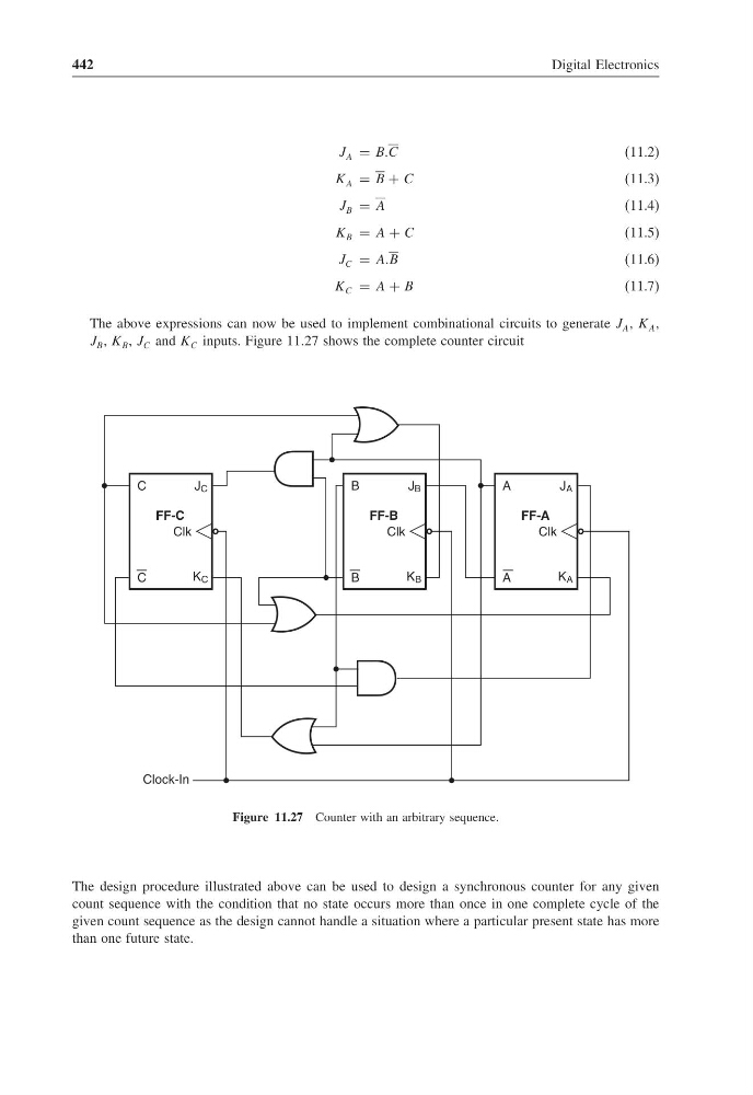
J B , K B , J C and K C inputs. Figure 11.27 shows the complete counter circuit
C
Clk
FF-C
J C
K C
C
Clk
FF-B
J B
K B
B
B
Clk
FF-A
J A
K A
A
A
Clock-In
Figure 11.27 Counter with an arbitrary sequence.
The design procedure illustrated above can be used to design a synchronous counter for any given
count sequence with the condition that no state occurs more than once in one complete cycle of the
given count sequence as the design cannot handle a situation where a particular present state has more
than one future state.
Digital Electronics
J A = BBC
(11.2)
K A = B + C
(11.3)
J B = A
(11.4)
K B = A + C
(11.5)
J C = AAB
(11.6)
K C = A + B
(11.7)
The above expressions can now be used to implement combinational circuits to generate J A , K A ,
J B , K B , J C and K C inputs. Figure 11.27 shows the complete counter circuit
C
Clk
FF-C
J C
K C
C
Clk
FF-B
J B
K B
B
B
Clk
FF-A
J A
K A
A
A
Clock-In
Figure 11.27 Counter with an arbitrary sequence.
The design procedure illustrated above can be used to design a synchronous counter for any given
count sequence with the condition that no state occurs more than once in one complete cycle of the
given count sequence as the design cannot handle a situation where a particular present state has more
than one future state.