

Counters and Registers
441
The circuit excitation table can be drawn very easily once we know the excitation table of the
flip-flop to be used for building the counter. For instance, let us look at the first row of the excitation
table (Table 11.9). The counter is in the 000 state and is to go to 010 on application of a clock
pulse. That is, the normal outputs of C, B and A flip-flops have to undergo ‘0’ to ‘0’, ‘0’ to ‘1’ and
‘0’ to ‘0’ transitions respectively. Referring to the excitation table of a J-K flip-flop, the desired
transitions can be realized if the logic status of J A , K A , J B , K B , J C and K C is as shown in the
excitation table.
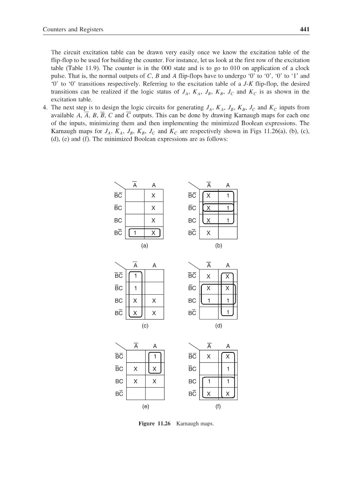
4. The next step is to design the logic circuits for generating J A , K A , J B , K B , J C and K C inputs from
available A, A, B, B, C and C outputs. This can be done by drawing Karnaugh maps for each one
of the inputs, minimizing them and then implementing the minimized Boolean expressions. The
Karnaugh maps for J A , K A , J B , K B , J C and K C are respectively shown in Figs 11.26(a), (b), (c),
(d), (e) and (f). The minimized Boolean expressions are as follows:
X
A
BC
1
X
X
X
A
BC
BC
BC
(a)
X
A
BC
1
X
X
X
A
BC
BC
BC
(b)
1
1
A
BC
X
X
A
BC
BC
BC
(c)
1
1
X
X
A
BC
X
A
BC
BC
BC
(d)
1
1
X
X
X
1
X
A
BC
1
X
X
A
BC
BC
BC
(e)
X
A
BC
X
X
A
BC
BC
BC
(f)
1
1
X
X
1
Figure 11.26 Karnaugh maps.
441
The circuit excitation table can be drawn very easily once we know the excitation table of the
flip-flop to be used for building the counter. For instance, let us look at the first row of the excitation
table (Table 11.9). The counter is in the 000 state and is to go to 010 on application of a clock
pulse. That is, the normal outputs of C, B and A flip-flops have to undergo ‘0’ to ‘0’, ‘0’ to ‘1’ and
‘0’ to ‘0’ transitions respectively. Referring to the excitation table of a J-K flip-flop, the desired
transitions can be realized if the logic status of J A , K A , J B , K B , J C and K C is as shown in the
excitation table.
4. The next step is to design the logic circuits for generating J A , K A , J B , K B , J C and K C inputs from
available A, A, B, B, C and C outputs. This can be done by drawing Karnaugh maps for each one
of the inputs, minimizing them and then implementing the minimized Boolean expressions. The
Karnaugh maps for J A , K A , J B , K B , J C and K C are respectively shown in Figs 11.26(a), (b), (c),
(d), (e) and (f). The minimized Boolean expressions are as follows:
X
A
BC
1
X
X
X
A
BC
BC
BC
(a)
X
A
BC
1
X
X
X
A
BC
BC
BC
(b)
1
1
A
BC
X
X
A
BC
BC
BC
(c)
1
1
X
X
A
BC
X
A
BC
BC
BC
(d)
1
1
X
X
X
1
X
A
BC
1
X
X
A
BC
BC
BC
(e)
X
A
BC
X
X
A
BC
BC
BC
(f)
1
1
X
X
1
Figure 11.26 Karnaugh maps.