

440
Digital Electronics
1. Determine the number of flip-flops required for the purpose. Identify the undesired states. In the
present case, the number of flip-flops required is 3 and the undesired states are 101 and 111
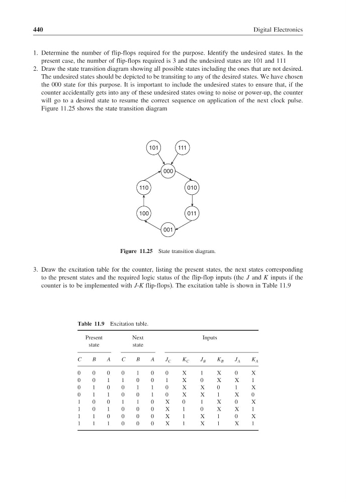
2. Draw the state transition diagram showing all possible states including the ones that are not desired.
The undesired states should be depicted to be transiting to any of the desired states. We have chosen
the 000 state for this purpose. It is important to include the undesired states to ensure that, if the
counter accidentally gets into any of these undesired states owing to noise or power-up, the counter
will go to a desired state to resume the correct sequence on application of the next clock pulse.
Figure 11.25 shows the state transition diagram
110
100
010
011
000
001
101
111
Figure 11.25 State transition diagram.
3. Draw the excitation table for the counter, listing the present states, the next states corresponding
to the present states and the required logic status of the flip-flop inputs (the J and K inputs if the
counter is to be implemented with J-K flip-flops). The excitation table is shown in Table 11.9
Table 11.9 Excitation table.
Present
Next
Inputs
state
state
C
B
A
C
B
A
J C
K C
J B
K B
J A
K A
0
0
0
0
1
0
0
X
1
X
0
X
0
0
1
1
0
0
1
X
0
X
X
1
0
1
0
0
1
1
0
X
X
0
1
X
0
1
1
0
0
1
0
X
X
1
X
0
1
0
0
1
1
0
X
0
1
X
0
X
1
0
1
0
0
0
X
1
0
X
X
1
1
1
0
0
0
0
X
1
X
1
0
X
1
1
1
0
0
0
X
1
X
1
X
1
Digital Electronics
1. Determine the number of flip-flops required for the purpose. Identify the undesired states. In the
present case, the number of flip-flops required is 3 and the undesired states are 101 and 111
2. Draw the state transition diagram showing all possible states including the ones that are not desired.
The undesired states should be depicted to be transiting to any of the desired states. We have chosen
the 000 state for this purpose. It is important to include the undesired states to ensure that, if the
counter accidentally gets into any of these undesired states owing to noise or power-up, the counter
will go to a desired state to resume the correct sequence on application of the next clock pulse.
Figure 11.25 shows the state transition diagram
110
100
010
011
000
001
101
111
Figure 11.25 State transition diagram.
3. Draw the excitation table for the counter, listing the present states, the next states corresponding
to the present states and the required logic status of the flip-flop inputs (the J and K inputs if the
counter is to be implemented with J-K flip-flops). The excitation table is shown in Table 11.9
Table 11.9 Excitation table.
Present
Next
Inputs
state
state
C
B
A
C
B
A
J C
K C
J B
K B
J A
K A
0
0
0
0
1
0
0
X
1
X
0
X
0
0
1
1
0
0
1
X
0
X
X
1
0
1
0
0
1
1
0
X
X
0
1
X
0
1
1
0
0
1
0
X
X
1
X
0
1
0
0
1
1
0
X
0
1
X
0
X
1
0
1
0
0
0
X
1
0
X
X
1
1
1
0
0
0
0
X
1
X
1
0
X
1
1
1
0
0
0
X
1
X
1
X
1