

Counters and Registers
443
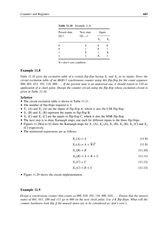
Table 11.10 Example 11.8.
Present state
(Q n )
Next state
(Q n + 1 )
Inputs
X 1
X 2
0
0
0
0
0
1
0
1
1
0
1
X
1
1
X
1
X = don’t care condition.
Example 11.8
Table 11.10 gives the excitation table of a certain flip-flop having X 1 and X 2 as its inputs. Draw the
circuit excitation table of an MOD-5 synchronous counter using this flip-flop for the count sequence
000, 001, 011, 101, 110, 000, If the present state is an undesired one, it should transit to 110 on
application of a clock pulse. Design the counter circuit using the flip-flop whose excitation circuit is
given in Table 11.10.
Solution
• The circuit excitation table is shown in Table 11.11.
• The number of flip-flops required is 3.
• X 1 (A) and X 2 (A) are the inputs of flip-flop A, which is also the LSB flip-flop.
• X 1 (B) and X 2 (B) represent the inputs to flip-flop B.
• X 1 (C) and X 2 (C) are the inputs to flip-flop C, which is also the MSB flip-flop.
• The next step is to draw Karnaugh maps, one each for different inputs to the three flip-flops.
• Figures 11.28(a) to (f) show the Karnaugh maps for X 1 (A), X 2 (A), X 1 (B), X 2 (B), X 1 (C) and X 2
(C) respectively.
• The minimized expressions are as follows:
X 1 AA = A
(11.8)
X 2 AA = A + BBC
(11.9)
X 1 BB = B
(11.10)
X 2 BB = A + B + C
(11.11)
X 1 CC = C
(11.12)
X 2 CC = B + C
(11.13)
• Figure 11.29 shows the circuit implementation.
Example 11.9
Design a synchronous counter that counts as 000, 010, 101, 110, 000, 010, Ensure that the unused
states of 001, 011, 100 and 111 go to 000 on the next clock pulse. Use J-K flip-flops. What will the
counter hardware look like if the unused states are to be considered as ‘don’t care’s.
443
Table 11.10 Example 11.8.
Present state
(Q n )
Next state
(Q n + 1 )
Inputs
X 1
X 2
0
0
0
0
0
1
0
1
1
0
1
X
1
1
X
1
X = don’t care condition.
Example 11.8
Table 11.10 gives the excitation table of a certain flip-flop having X 1 and X 2 as its inputs. Draw the
circuit excitation table of an MOD-5 synchronous counter using this flip-flop for the count sequence
000, 001, 011, 101, 110, 000, If the present state is an undesired one, it should transit to 110 on
application of a clock pulse. Design the counter circuit using the flip-flop whose excitation circuit is
given in Table 11.10.
Solution
• The circuit excitation table is shown in Table 11.11.
• The number of flip-flops required is 3.
• X 1 (A) and X 2 (A) are the inputs of flip-flop A, which is also the LSB flip-flop.
• X 1 (B) and X 2 (B) represent the inputs to flip-flop B.
• X 1 (C) and X 2 (C) are the inputs to flip-flop C, which is also the MSB flip-flop.
• The next step is to draw Karnaugh maps, one each for different inputs to the three flip-flops.
• Figures 11.28(a) to (f) show the Karnaugh maps for X 1 (A), X 2 (A), X 1 (B), X 2 (B), X 1 (C) and X 2
(C) respectively.
• The minimized expressions are as follows:
X 1 AA = A
(11.8)
X 2 AA = A + BBC
(11.9)
X 1 BB = B
(11.10)
X 2 BB = A + B + C
(11.11)
X 1 CC = C
(11.12)
X 2 CC = B + C
(11.13)
• Figure 11.29 shows the circuit implementation.
Example 11.9
Design a synchronous counter that counts as 000, 010, 101, 110, 000, 010, Ensure that the unused
states of 001, 011, 100 and 111 go to 000 on the next clock pulse. Use J-K flip-flops. What will the
counter hardware look like if the unused states are to be considered as ‘don’t care’s.