

Counters and Registers
437
Q3
Q2
Q1
Q0
U/D
CE
GND
CP
RC
TC
74190
V CC PL
P
A
B
C
D
Q3
Q2
Q1
Q0
U/D
CE
GND
CP
RC
TC
74190
V CC
+V CC
PL
P
H
G
F
E
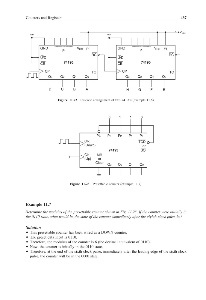
Figure 11.22 Cascade arrangement of two 74190s (example 11.6).
Q3
Q2
Q1
Q0
Clk
(Down)
Clk
(Up)
74193
1
MR
or
Clear
P3
P2
P1
P0
PL
TCD
or
BO
0
1
0
1
Figure 11.23 Presettable counter (example 11.7).
Example 11.7
Determine the modulus of the presettable counter shown in Fig. 11.23. If the counter were initially in
the 0110 state, what would be the state of the counter immediately after the eighth clock pulse be?
Solution
• This presettable counter has been wired as a DOWN counter.
• The preset data input is 0110.
• Therefore, the modulus of the counter is 6 (the decimal equivalent of 0110).
• Now, the counter is initially in the 0110 state.
• Therefore, at the end of the sixth clock pulse, immediately after the leading edge of the sixth clock
pulse, the counter will be in the 0000 state.
437
Q3
Q2
Q1
Q0
U/D
CE
GND
CP
RC
TC
74190
V CC PL
P
A
B
C
D
Q3
Q2
Q1
Q0
U/D
CE
GND
CP
RC
TC
74190
V CC
+V CC
PL
P
H
G
F
E
Figure 11.22 Cascade arrangement of two 74190s (example 11.6).
Q3
Q2
Q1
Q0
Clk
(Down)
Clk
(Up)
74193
1
MR
or
Clear
P3
P2
P1
P0
PL
TCD
or
BO
0
1
0
1
Figure 11.23 Presettable counter (example 11.7).
Example 11.7
Determine the modulus of the presettable counter shown in Fig. 11.23. If the counter were initially in
the 0110 state, what would be the state of the counter immediately after the eighth clock pulse be?
Solution
• This presettable counter has been wired as a DOWN counter.
• The preset data input is 0110.
• Therefore, the modulus of the counter is 6 (the decimal equivalent of 0110).
• Now, the counter is initially in the 0110 state.
• Therefore, at the end of the sixth clock pulse, immediately after the leading edge of the sixth clock
pulse, the counter will be in the 0000 state.