

436
Digital Electronics
BCD
Counter
Clk
D C B A
1000's Counter
BCD
Counter
Clk
D C B A
100's Counter
BCD
Counter
Clk
D C B A
10's Counter
BCD
Counter
Clk
D C B A
1's Counter
Input
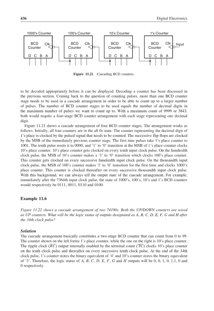
Figure 11.21 Cascading BCD counters.
to be decoded appropriately before it can be displayed. Decoding a counter has been discussed in
the previous section. Coming back to the question of counting pulses, more than one BCD counter
stage needs to be used in a cascade arrangement in order to be able to count up to a larger number
of pulses. The number of BCD counter stages to be used equals the number of decimal digits in
the maximum number of pulses we want to count up to. With a maximum count of 9999 or 3843,
both would require a four-stage BCD counter arrangement with each stage representing one decimal
digit.
Figure 11.21 shows a cascade arrangement of four BCD counter stages. The arrangement works as
follows. Initially, all four counters are in the all 0s state. The counter representing the decimal digit of
1’s place is clocked by the pulsed signal that needs to be counted. The successive flip-flops are clocked
by the MSB of the immediately previous counter stage. The first nine pulses take 1’s place counter to
1001. The tenth pulse resets it to 0000, and ‘1’ to ‘0’ transition at the MSB of 1’s place counter clocks
10’s place counter. 10’s place counter gets clocked on every tenth input clock pulse. On the hundredth
clock pulse, the MSB of 10’s counter makes a ‘1’ to ‘0’ transition which clocks 100’s place counter.
This counter gets clocked on every successive hundredth input clock pulse. On the thousandth input
clock pulse, the MSB of 100’s counter makes ‘l’ to ‘0’ transition for the first time and clocks 1000’s
place counter. This counter is clocked thereafter on every successive thousandth input clock pulse.
With this background, we can always tell the output state of the cascade arrangement. For example,
immediately after the 7364th input clock pulse, the state of 1000’s, 100’s, 10’s and 1’s BCD counters
would respectively be 0111, 0011, 0110 and 0100.
Example 11.6
Figure 11.22 shows a cascade arrangement of two 74190s. Both the UP/DOWN counters are wired
as UP counters. What will be the logic status of outputs designated as A, B, C, D, E, F, G and H after
the 34th clock pulse?
Solution
The cascade arrangement basically constitutes a two-stage BCD counter that can count from 0 to 99.
The counter shown on the left forms 1’s place counter, while the one on the right is 10’s place counter.
The ripple clock (RCC output internally enabled by the terminal count TC clocks 10’s place counter
on the tenth clock pulse and thereafter on every successive tenth clock pulse. At the end of the 34th
clock pulse, 1’s counter stores the binary equivalent of ‘4’ and 10’s counter stores the binary equivalent
of ‘3’. Therefore, the logic status of A, B, C, D, E, F , G and H outputs will be 0, 0, 1, 0, 1,1, 0 and
0 respectively.
Digital Electronics
BCD
Counter
Clk
D C B A
1000's Counter
BCD
Counter
Clk
D C B A
100's Counter
BCD
Counter
Clk
D C B A
10's Counter
BCD
Counter
Clk
D C B A
1's Counter
Input
Figure 11.21 Cascading BCD counters.
to be decoded appropriately before it can be displayed. Decoding a counter has been discussed in
the previous section. Coming back to the question of counting pulses, more than one BCD counter
stage needs to be used in a cascade arrangement in order to be able to count up to a larger number
of pulses. The number of BCD counter stages to be used equals the number of decimal digits in
the maximum number of pulses we want to count up to. With a maximum count of 9999 or 3843,
both would require a four-stage BCD counter arrangement with each stage representing one decimal
digit.
Figure 11.21 shows a cascade arrangement of four BCD counter stages. The arrangement works as
follows. Initially, all four counters are in the all 0s state. The counter representing the decimal digit of
1’s place is clocked by the pulsed signal that needs to be counted. The successive flip-flops are clocked
by the MSB of the immediately previous counter stage. The first nine pulses take 1’s place counter to
1001. The tenth pulse resets it to 0000, and ‘1’ to ‘0’ transition at the MSB of 1’s place counter clocks
10’s place counter. 10’s place counter gets clocked on every tenth input clock pulse. On the hundredth
clock pulse, the MSB of 10’s counter makes a ‘1’ to ‘0’ transition which clocks 100’s place counter.
This counter gets clocked on every successive hundredth input clock pulse. On the thousandth input
clock pulse, the MSB of 100’s counter makes ‘l’ to ‘0’ transition for the first time and clocks 1000’s
place counter. This counter is clocked thereafter on every successive thousandth input clock pulse.
With this background, we can always tell the output state of the cascade arrangement. For example,
immediately after the 7364th input clock pulse, the state of 1000’s, 100’s, 10’s and 1’s BCD counters
would respectively be 0111, 0011, 0110 and 0100.
Example 11.6
Figure 11.22 shows a cascade arrangement of two 74190s. Both the UP/DOWN counters are wired
as UP counters. What will be the logic status of outputs designated as A, B, C, D, E, F, G and H after
the 34th clock pulse?
Solution
The cascade arrangement basically constitutes a two-stage BCD counter that can count from 0 to 99.
The counter shown on the left forms 1’s place counter, while the one on the right is 10’s place counter.
The ripple clock (RCC output internally enabled by the terminal count TC clocks 10’s place counter
on the tenth clock pulse and thereafter on every successive tenth clock pulse. At the end of the 34th
clock pulse, 1’s counter stores the binary equivalent of ‘4’ and 10’s counter stores the binary equivalent
of ‘3’. Therefore, the logic status of A, B, C, D, E, F , G and H outputs will be 0, 0, 1, 0, 1,1, 0 and
0 respectively.