

432
Digital Electronics
Table 11.6 Functional table of the decoder of Fig. 11.16.
Decimal number
BCD input
Decimal output
D
C
B
A
0
1
2
3
4
5
6
7
8
9
0
L
L
L
L
L
H
H
H
H
H
H
H
H
H
1
L
L
L
H
H
L
H
H
H
H
H
H
H
H
2
L
L
H
L
H
H
L
H
H
H
H
H
H
H
3
L
L
H
H
H
H
H
L
H
H
H
H
H
H
4
L
H
L
L
H
H
H
H
L
H
H
H
H
H
5
L
H
L
H
H
H
H
H
H
L
H
H
H
H
6
L
H
H
L
H
H
H
H
H
H
L
H
H
H
7
L
H
H
H
H
H
H
H
H
H
H
L
H
H
8
H
L
L
L
H
H
H
H
H
H
H
H
L
H
9
H
L
L
H
H
H
H
H
H
H
H
H
H
L
Invalid
H
L
H
L
H
H
H
H
H
H
H
H
H
H
Invalid
H
L
H
H
H
H
H
H
H
H
H
H
H
H
Invalid
H
H
L
L
H
H
H
H
H
H
H
H
H
H
Invalid
H
H
L
H
H
H
H
H
H
H
H
H
H
H
Invalid
H
H
H
L
H
H
H
H
H
H
H
H
H
H
Invalid
H
H
H
H
H
H
H
H
H
H
H
H
H
H
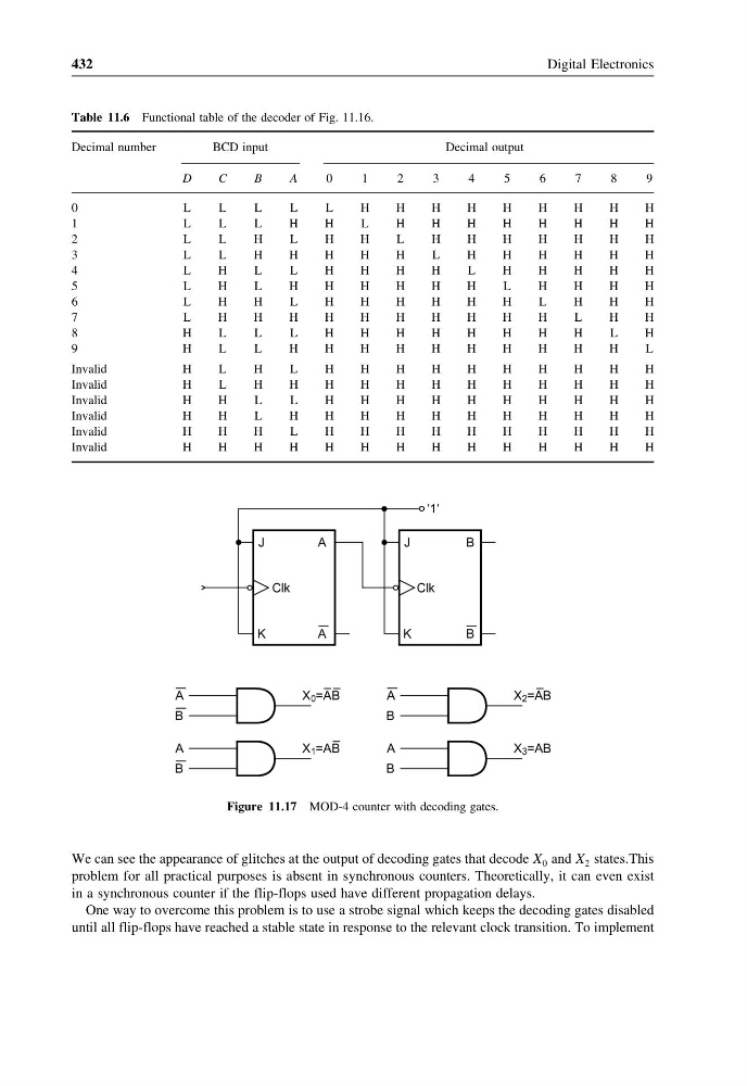
Figure 11.17 MOD-4 counter with decoding gates.
We can see the appearance of glitches at the output of decoding gates that decode X 0 and X 2 statesThis
problem for all practical purposes is absent in synchronous counters. Theoretically, it can even exist
in a synchronous counter if the flip-flops used have different propagation delays.
One way to overcome this problem is to use a strobe signal which keeps the decoding gates disabled
until all flip-flops have reached a stable state in response to the relevant clock transition. To implement
Digital Electronics
Table 11.6 Functional table of the decoder of Fig. 11.16.
Decimal number
BCD input
Decimal output
D
C
B
A
0
1
2
3
4
5
6
7
8
9
0
L
L
L
L
L
H
H
H
H
H
H
H
H
H
1
L
L
L
H
H
L
H
H
H
H
H
H
H
H
2
L
L
H
L
H
H
L
H
H
H
H
H
H
H
3
L
L
H
H
H
H
H
L
H
H
H
H
H
H
4
L
H
L
L
H
H
H
H
L
H
H
H
H
H
5
L
H
L
H
H
H
H
H
H
L
H
H
H
H
6
L
H
H
L
H
H
H
H
H
H
L
H
H
H
7
L
H
H
H
H
H
H
H
H
H
H
L
H
H
8
H
L
L
L
H
H
H
H
H
H
H
H
L
H
9
H
L
L
H
H
H
H
H
H
H
H
H
H
L
Invalid
H
L
H
L
H
H
H
H
H
H
H
H
H
H
Invalid
H
L
H
H
H
H
H
H
H
H
H
H
H
H
Invalid
H
H
L
L
H
H
H
H
H
H
H
H
H
H
Invalid
H
H
L
H
H
H
H
H
H
H
H
H
H
H
Invalid
H
H
H
L
H
H
H
H
H
H
H
H
H
H
Invalid
H
H
H
H
H
H
H
H
H
H
H
H
H
H
Figure 11.17 MOD-4 counter with decoding gates.
We can see the appearance of glitches at the output of decoding gates that decode X 0 and X 2 statesThis
problem for all practical purposes is absent in synchronous counters. Theoretically, it can even exist
in a synchronous counter if the flip-flops used have different propagation delays.
One way to overcome this problem is to use a strobe signal which keeps the decoding gates disabled
until all flip-flops have reached a stable state in response to the relevant clock transition. To implement