

Counters and Registers
433
Clock
A-Output
B-Output
X 0
X 1
X 2
X 3
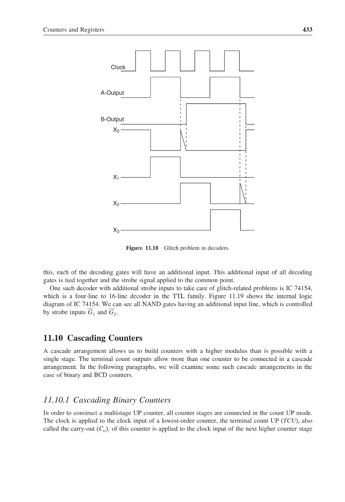
Figure 11.18 Glitch problem in decoders.
this, each of the decoding gates will have an additional input. This additional input of all decoding
gates is tied together and the strobe signal applied to the common point.
One such decoder with additional strobe inputs to take care of glitch-related problems is IC 74154,
which is a four-line to 16-line decoder in the TTL family. Figure 11.19 shows the internal logic
diagram of IC 74154. We can see all NAND gates having an additional input line, which is controlled
by strobe inputs G 1 and G 2 .
11.10 Cascading Counters
A cascade arrangement allows us to build counters with a higher modulus than is possible with a
single stage. The terminal count outputs allow more than one counter to be connected in a cascade
arrangement. In the following paragraphs, we will examine some such cascade arrangements in the
case of binary and BCD counters.
11.10.1 Cascading Binary Counters
In order to construct a multistage UP counter, all counter stages are connected in the count UP mode.
The clock is applied to the clock input of a lowest-order counter, the terminal count UP (TCU), also
called the carry-out (C o , of this counter is applied to the clock input of the next higher counter stage
433
Clock
A-Output
B-Output
X 0
X 1
X 2
X 3
Figure 11.18 Glitch problem in decoders.
this, each of the decoding gates will have an additional input. This additional input of all decoding
gates is tied together and the strobe signal applied to the common point.
One such decoder with additional strobe inputs to take care of glitch-related problems is IC 74154,
which is a four-line to 16-line decoder in the TTL family. Figure 11.19 shows the internal logic
diagram of IC 74154. We can see all NAND gates having an additional input line, which is controlled
by strobe inputs G 1 and G 2 .
11.10 Cascading Counters
A cascade arrangement allows us to build counters with a higher modulus than is possible with a
single stage. The terminal count outputs allow more than one counter to be connected in a cascade
arrangement. In the following paragraphs, we will examine some such cascade arrangements in the
case of binary and BCD counters.
11.10.1 Cascading Binary Counters
In order to construct a multistage UP counter, all counter stages are connected in the count UP mode.
The clock is applied to the clock input of a lowest-order counter, the terminal count UP (TCU), also
called the carry-out (C o , of this counter is applied to the clock input of the next higher counter stage