

Counters and Registers
431
Output0
Output1
Output2
Output3
Output4
Output5
Output6
Output7
Output8
Output9
A
A
B
B
C
C
D
D
Input D
Input C
Input B
Input A
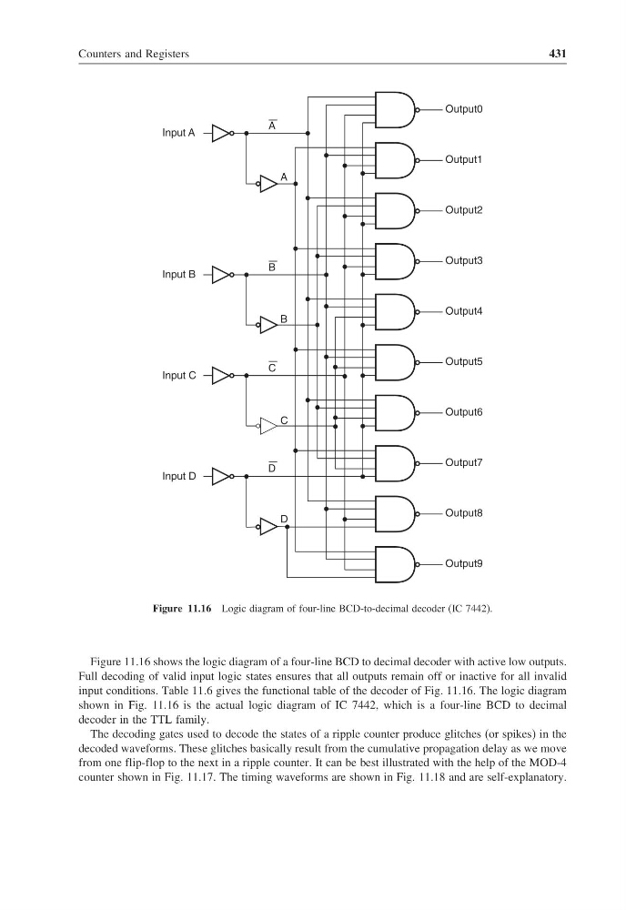
Figure 11.16 Logic diagram of four-line BCD-to-decimal decoder (IC 7442).
Figure 11.16 shows the logic diagram of a four-line BCD to decimal decoder with active low outputs.
Full decoding of valid input logic states ensures that all outputs remain off or inactive for all invalid
input conditions. Table 11.6 gives the functional table of the decoder of Fig. 11.16. The logic diagram
shown in Fig. 11.16 is the actual logic diagram of IC 7442, which is a four-line BCD to decimal
decoder in the TTL family.
The decoding gates used to decode the states of a ripple counter produce glitches (or spikes) in the
decoded waveforms. These glitches basically result from the cumulative propagation delay as we move
from one flip-flop to the next in a ripple counter. It can be best illustrated with the help of the MOD-4
counter shown in Fig. 11.17. The timing waveforms are shown in Fig. 11.18 and are self-explanatory.
431
Output0
Output1
Output2
Output3
Output4
Output5
Output6
Output7
Output8
Output9
A
A
B
B
C
C
D
D
Input D
Input C
Input B
Input A
Figure 11.16 Logic diagram of four-line BCD-to-decimal decoder (IC 7442).
Figure 11.16 shows the logic diagram of a four-line BCD to decimal decoder with active low outputs.
Full decoding of valid input logic states ensures that all outputs remain off or inactive for all invalid
input conditions. Table 11.6 gives the functional table of the decoder of Fig. 11.16. The logic diagram
shown in Fig. 11.16 is the actual logic diagram of IC 7442, which is a four-line BCD to decimal
decoder in the TTL family.
The decoding gates used to decode the states of a ripple counter produce glitches (or spikes) in the
decoded waveforms. These glitches basically result from the cumulative propagation delay as we move
from one flip-flop to the next in a ripple counter. It can be best illustrated with the help of the MOD-4
counter shown in Fig. 11.17. The timing waveforms are shown in Fig. 11.18 and are self-explanatory.