

428
Digital Electronics
Clk(UP)
Clk(Down)
TCD
TCU
P 3 P 2 P 1 P 0
Q 3
Q 2
Q 1
Q 0
PL
0
1
1
0
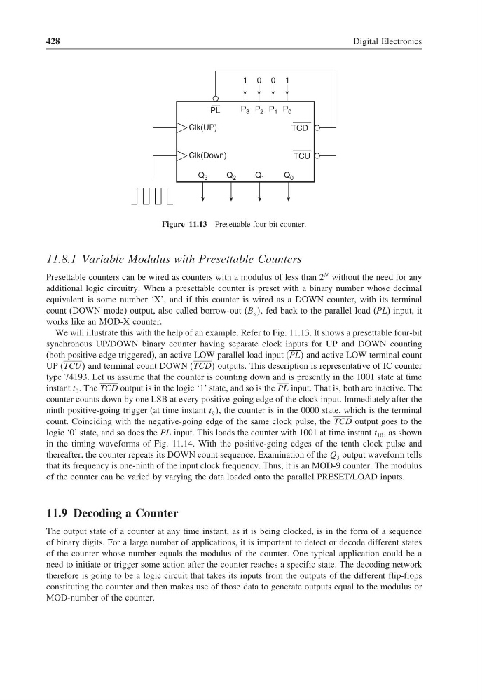
Figure 11.13 Presettable four-bit counter.
11.8.1 Variable Modulus with Presettable Counters
Presettable counters can be wired as counters with a modulus of less than 2
N without the need for any
additional logic circuitry. When a presettable counter is preset with a binary number whose decimal
equivalent is some number ‘X’, and if this counter is wired as a DOWN counter, with its terminal
count (DOWN mode) output, also called borrow-out (B o , fed back to the parallel load (PL) input, it
works like an MOD-X counter.
We will illustrate this with the help of an example. Refer to Fig. 11.13. It shows a presettable four-bit
synchronous UP/DOWN binary counter having separate clock inputs for UP and DOWN counting
(both positive edge triggered), an active LOW parallel load input (PLL and active LOW terminal count
UP (TCU U and terminal count DOWN (TCDD outputs. This description is representative of IC counter
type 74193. Let us assume that the counter is counting down and is presently in the 1001 state at time
instant t 0 . The TCD output is in the logic ‘1’ state, and so is the PL input. That is, both are inactive. The
counter counts down by one LSB at every positive-going edge of the clock input. Immediately after the
ninth positive-going trigger (at time instant t 9 , the counter is in the 0000 state, which is the terminal
count. Coinciding with the negative-going edge of the same clock pulse, the TCD output goes to the
logic ‘0’ state, and so does the PL input. This loads the counter with 1001 at time instant t 10 , as shown
in the timing waveforms of Fig. 11.14. With the positive-going edges of the tenth clock pulse and
thereafter, the counter repeats its DOWN count sequence. Examination of the Q 3 output waveform tells
that its frequency is one-ninth of the input clock frequency. Thus, it is an MOD-9 counter. The modulus
of the counter can be varied by varying the data loaded onto the parallel PRESET/LOAD inputs.
11.9 Decoding a Counter
The output state of a counter at any time instant, as it is being clocked, is in the form of a sequence
of binary digits. For a large number of applications, it is important to detect or decode different states
of the counter whose number equals the modulus of the counter. One typical application could be a
need to initiate or trigger some action after the counter reaches a specific state. The decoding network
therefore is going to be a logic circuit that takes its inputs from the outputs of the different flip-flops
constituting the counter and then makes use of those data to generate outputs equal to the modulus or
MOD-number of the counter.
Digital Electronics
Clk(UP)
Clk(Down)
TCD
TCU
P 3 P 2 P 1 P 0
Q 3
Q 2
Q 1
Q 0
PL
0
1
1
0
Figure 11.13 Presettable four-bit counter.
11.8.1 Variable Modulus with Presettable Counters
Presettable counters can be wired as counters with a modulus of less than 2
N without the need for any
additional logic circuitry. When a presettable counter is preset with a binary number whose decimal
equivalent is some number ‘X’, and if this counter is wired as a DOWN counter, with its terminal
count (DOWN mode) output, also called borrow-out (B o , fed back to the parallel load (PL) input, it
works like an MOD-X counter.
We will illustrate this with the help of an example. Refer to Fig. 11.13. It shows a presettable four-bit
synchronous UP/DOWN binary counter having separate clock inputs for UP and DOWN counting
(both positive edge triggered), an active LOW parallel load input (PLL and active LOW terminal count
UP (TCU U and terminal count DOWN (TCDD outputs. This description is representative of IC counter
type 74193. Let us assume that the counter is counting down and is presently in the 1001 state at time
instant t 0 . The TCD output is in the logic ‘1’ state, and so is the PL input. That is, both are inactive. The
counter counts down by one LSB at every positive-going edge of the clock input. Immediately after the
ninth positive-going trigger (at time instant t 9 , the counter is in the 0000 state, which is the terminal
count. Coinciding with the negative-going edge of the same clock pulse, the TCD output goes to the
logic ‘0’ state, and so does the PL input. This loads the counter with 1001 at time instant t 10 , as shown
in the timing waveforms of Fig. 11.14. With the positive-going edges of the tenth clock pulse and
thereafter, the counter repeats its DOWN count sequence. Examination of the Q 3 output waveform tells
that its frequency is one-ninth of the input clock frequency. Thus, it is an MOD-9 counter. The modulus
of the counter can be varied by varying the data loaded onto the parallel PRESET/LOAD inputs.
11.9 Decoding a Counter
The output state of a counter at any time instant, as it is being clocked, is in the form of a sequence
of binary digits. For a large number of applications, it is important to detect or decode different states
of the counter whose number equals the modulus of the counter. One typical application could be a
need to initiate or trigger some action after the counter reaches a specific state. The decoding network
therefore is going to be a logic circuit that takes its inputs from the outputs of the different flip-flops
constituting the counter and then makes use of those data to generate outputs equal to the modulus or
MOD-number of the counter.