

Counters and Registers
427
Presettable counters can be UP counters, DOWN counters or UP/DOWN counters. Additional
inputs/outputs available on a presettable UP/DOWN counter usually include PRESET inputs, from
where any desired count can be loaded, parallel load (PL) inputs, which when active allow the PRESET
inputs to be loaded onto the counter outputs, and terminal count (TC) outputs, which become active
when the counter reaches the terminal count.
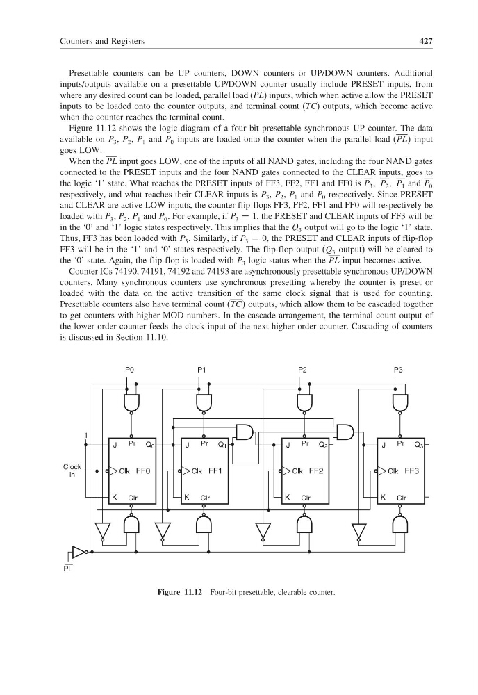
Figure 11.12 shows the logic diagram of a four-bit presettable synchronous UP counter. The data
available on P 3 , P 2 , P 1 and P 0 inputs are loaded onto the counter when the parallel load (PLL input
goes LOW.
When the PL input goes LOW, one of the inputs of all NAND gates, including the four NAND gates
connected to the PRESET inputs and the four NAND gates connected to the CLEAR inputs, goes to
the logic ‘1’ state. What reaches the PRESET inputs of FF3, FF2, FF1 and FF0 is P 3 P 2 P 1 and P 0
respectively, and what reaches their CLEAR inputs is P 3 , P 2 , P 1 and P 0 respectively. Since PRESET
and CLEAR are active LOW inputs, the counter flip-flops FF3, FF2, FF1 and FF0 will respectively be
loaded with P 3 , P 2 , P 1 and P 0 . For example, if P 3 = 1, the PRESET and CLEAR inputs of FF3 will be
in the ‘0’ and ‘1’ logic states respectively. This implies that the Q 3 output will go to the logic ‘1’ state.
Thus, FF3 has been loaded with P 3 . Similarly, if P 3 = 0, the PRESET and CLEAR inputs of flip-flop
FF3 will be in the ‘1’ and ‘0’ states respectively. The flip-flop output (Q 3 output) will be cleared to
the ‘0’ state. Again, the flip-flop is loaded with P 3 logic status when the PL input becomes active.
Counter ICs 74190, 74191, 74192 and 74193 are asynchronously presettable synchronous UP/DOWN
counters. Many synchronous counters use synchronous presetting whereby the counter is preset or
loaded with the data on the active transition of the same clock signal that is used for counting.
Presettable counters also have terminal count (TCC outputs, which allow them to be cascaded together
to get counters with higher MOD numbers. In the cascade arrangement, the terminal count output of
the lower-order counter feeds the clock input of the next higher-order counter. Cascading of counters
is discussed in Section 11.10.
Q 0
J
K
Clk FF0
Pr
Clr
P0
Q 1
J
K
Clk FF1
Pr
Clr
P1
Q 2
J
K
Clk FF2
Pr
Clr
P2
Q 3
J
K
Clk FF3
Pr
Clr
P3
PL
Clock
in
1
Figure 11.12 Four-bit presettable, clearable counter.
427
Presettable counters can be UP counters, DOWN counters or UP/DOWN counters. Additional
inputs/outputs available on a presettable UP/DOWN counter usually include PRESET inputs, from
where any desired count can be loaded, parallel load (PL) inputs, which when active allow the PRESET
inputs to be loaded onto the counter outputs, and terminal count (TC) outputs, which become active
when the counter reaches the terminal count.
Figure 11.12 shows the logic diagram of a four-bit presettable synchronous UP counter. The data
available on P 3 , P 2 , P 1 and P 0 inputs are loaded onto the counter when the parallel load (PLL input
goes LOW.
When the PL input goes LOW, one of the inputs of all NAND gates, including the four NAND gates
connected to the PRESET inputs and the four NAND gates connected to the CLEAR inputs, goes to
the logic ‘1’ state. What reaches the PRESET inputs of FF3, FF2, FF1 and FF0 is P 3 P 2 P 1 and P 0
respectively, and what reaches their CLEAR inputs is P 3 , P 2 , P 1 and P 0 respectively. Since PRESET
and CLEAR are active LOW inputs, the counter flip-flops FF3, FF2, FF1 and FF0 will respectively be
loaded with P 3 , P 2 , P 1 and P 0 . For example, if P 3 = 1, the PRESET and CLEAR inputs of FF3 will be
in the ‘0’ and ‘1’ logic states respectively. This implies that the Q 3 output will go to the logic ‘1’ state.
Thus, FF3 has been loaded with P 3 . Similarly, if P 3 = 0, the PRESET and CLEAR inputs of flip-flop
FF3 will be in the ‘1’ and ‘0’ states respectively. The flip-flop output (Q 3 output) will be cleared to
the ‘0’ state. Again, the flip-flop is loaded with P 3 logic status when the PL input becomes active.
Counter ICs 74190, 74191, 74192 and 74193 are asynchronously presettable synchronous UP/DOWN
counters. Many synchronous counters use synchronous presetting whereby the counter is preset or
loaded with the data on the active transition of the same clock signal that is used for counting.
Presettable counters also have terminal count (TCC outputs, which allow them to be cascaded together
to get counters with higher MOD numbers. In the cascade arrangement, the terminal count output of
the lower-order counter feeds the clock input of the next higher-order counter. Cascading of counters
is discussed in Section 11.10.
Q 0
J
K
Clk FF0
Pr
Clr
P0
Q 1
J
K
Clk FF1
Pr
Clr
P1
Q 2
J
K
Clk FF2
Pr
Clr
P2
Q 3
J
K
Clk FF3
Pr
Clr
P3
PL
Clock
in
1
Figure 11.12 Four-bit presettable, clearable counter.