

Counters and Registers
419
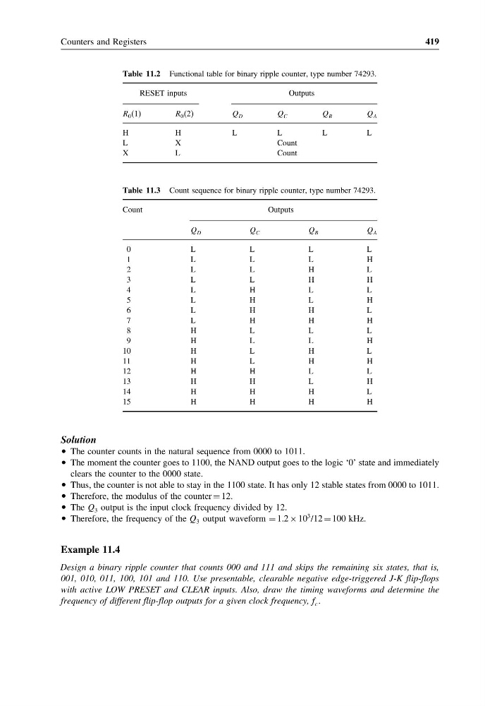
Table 11.2 Functional table for binary ripple counter, type number 74293.
RESET inputs
Outputs
R 0 (1)
R 0 (2)
Q D
Q C
Q B
Q A
H
H
L
L
L
L
L
X
Count
X
L
Count
Table 11.3 Count sequence for binary ripple counter, type number 74293.
Count
Outputs
Q D
Q C
Q B
Q A
0
L
L
L
L
1
L
L
L
H
2
L
L
H
L
3
L
L
H
H
4
L
H
L
L
5
L
H
L
H
6
L
H
H
L
7
L
H
H
H
8
H
L
L
L
9
H
L
L
H
10
H
L
H
L
11
H
L
H
H
12
H
H
L
L
13
H
H
L
H
14
H
H
H
L
15
H
H
H
H
Solution
• The counter counts in the natural sequence from 0000 to 1011.
• The moment the counter goes to 1100, the NAND output goes to the logic ‘0’ state and immediately
clears the counter to the 0000 state.
• Thus, the counter is not able to stay in the 1100 state. It has only 12 stable states from 0000 to 1011.
• Therefore, the modulus of the counter = 12.
• The Q 3 output is the input clock frequency divided by 12.
• Therefore, the frequency of the Q 3 output waveform = 1.2 × 10
3 /12 = 100 kHz.
Example 11.4
Design a binary ripple counter that counts 000 and 111 and skips the remaining six states, that is,
001, 010, 011, 100, 101 and 110. Use presentable, clearable negative edge-triggered J-K flip-flops
with active LOW PRESET and CLEAR inputs. Also, draw the timing waveforms and determine the
frequency of different flip-flop outputs for a given clock frequency, f c
419
Table 11.2 Functional table for binary ripple counter, type number 74293.
RESET inputs
Outputs
R 0 (1)
R 0 (2)
Q D
Q C
Q B
Q A
H
H
L
L
L
L
L
X
Count
X
L
Count
Table 11.3 Count sequence for binary ripple counter, type number 74293.
Count
Outputs
Q D
Q C
Q B
Q A
0
L
L
L
L
1
L
L
L
H
2
L
L
H
L
3
L
L
H
H
4
L
H
L
L
5
L
H
L
H
6
L
H
H
L
7
L
H
H
H
8
H
L
L
L
9
H
L
L
H
10
H
L
H
L
11
H
L
H
H
12
H
H
L
L
13
H
H
L
H
14
H
H
H
L
15
H
H
H
H
Solution
• The counter counts in the natural sequence from 0000 to 1011.
• The moment the counter goes to 1100, the NAND output goes to the logic ‘0’ state and immediately
clears the counter to the 0000 state.
• Thus, the counter is not able to stay in the 1100 state. It has only 12 stable states from 0000 to 1011.
• Therefore, the modulus of the counter = 12.
• The Q 3 output is the input clock frequency divided by 12.
• Therefore, the frequency of the Q 3 output waveform = 1.2 × 10
3 /12 = 100 kHz.
Example 11.4
Design a binary ripple counter that counts 000 and 111 and skips the remaining six states, that is,
001, 010, 011, 100, 101 and 110. Use presentable, clearable negative edge-triggered J-K flip-flops
with active LOW PRESET and CLEAR inputs. Also, draw the timing waveforms and determine the
frequency of different flip-flop outputs for a given clock frequency, f c